|
|
A and B Vectors
This is probably the most complex part in the 5X machine definition - the relation between the axes and the machine geometry.
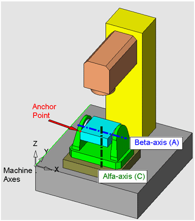
GPP2 uses two vectors to define the relationship between the axes and from the table axis to the Anchor Point (also known as the red point). In rotating head machines, the vectors are used to define the relationship to the spindle center point.
These vectors are only important for machines with no RTCP - so that GPP2 can do the necessary corrections itself. With RTCP, these vectors are ignored. However, they always affect the output to the machine simulator, so it is highly recommended that they are set properly to allow the use of the machine simulator.
The vectors are used differently based on the machine type:
|
Machine Type |
Vector A M5_A_VECX M5_A_VECY M5_A_VECZ |
Vector B M5_B_VECX M5_B_VECY M5_B_VECZ |
|
Table - Table |
From the center of the alpha rotation axis to the center of the beta rotation axis |
From the end of the A vector to the Anchor Point. |
|
Table - Head |
From the center of the alpha rotation axis to the Anchor Point |
From the center of the beta rotation axis to the spindle center point. |
|
Head - Head |
From the center of the alpha rotation axis to the center of the beta rotation axis |
From the end of the A vector to the spindle center point. |
The center of an axis is not really a single point - it is a line - the rotation axis itself. So, where should a vector actually start? Surely, picking different points along the alpha rotation axis as the start point of the A vector will result in different vectors. So, which start point is the right one? Interestingly, all of them are equally valid. GPP2 has a mechanism that deals with such vectors regardless of their start point along the axis. Therefore, the most convenient point should be used as the start point (For example, the point just under the beta axis).
In table-table or head-head machines, the B vector must start at the end point of the A vector.
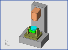
The following diagram shows a simple case of a table-table machine. The alpha axis is around X, and the beta axis is around Z.
|
|
|
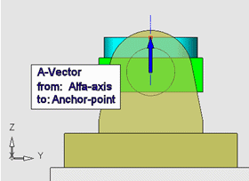
As can be seen from the side view, the A vector extends from the center of the alpha axis to the top center of the table. The Anchor Point is at the center of the table, so the B vector is zero.
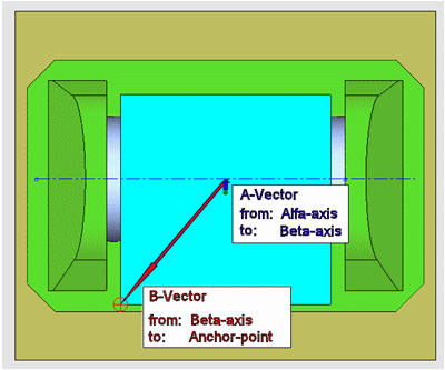
The following diagrams illustrate the A and B vectors in a more complex table-table machine, with an alpha Z axis and a beta X axis.
|
General View and Side (X) View |
|
|
|
|
|
Top View and Side (Y) View |
|
|
|
|
Notes:
-
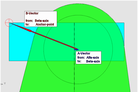
This is a fairly complex situation, since the center of the beta axis (X) is not located above the center of the alpha axis (Z). It is somewhat shifted on the Y axis. That's why both vectors are non-zero in this example.
-
Note the start point of the A vector (along the alpha Z axis). It is chosen at the same height as the beta axis, for simplicity.
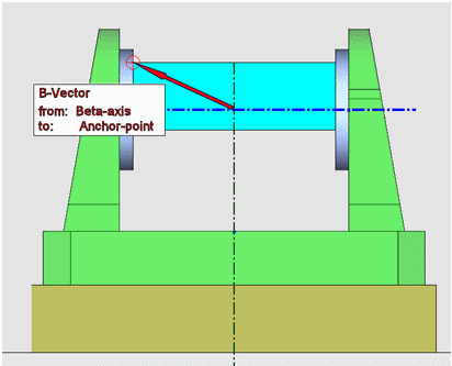
Now consider a Head-head machine, shown below. Here, the A vector is vertical, connecting the alpha axis center to the beta axis center.
|
|
|
The B vector connects the beta rotation axis to the spindle center point. Here, we chose a B vector that is not perpendicular to the rotation axis. As explained before, the vector can start anywhere along the axis rotation line, as long as it starts where the A vector ends.
Note that when a tool will be later added to this machine, the tool "vector" will actually be added to the B vector, since it effectively extends the lever of the beta axis.
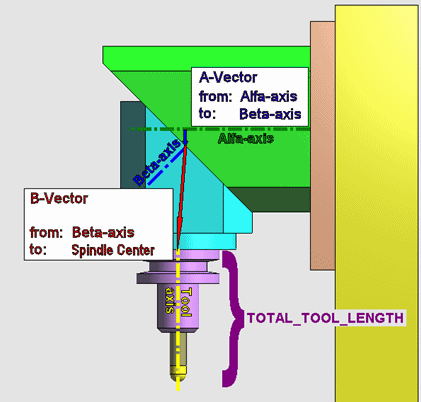
Finally, consider the Table-head machine shown below.
|
|
|
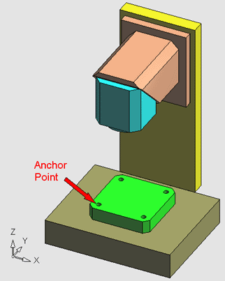
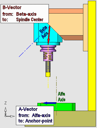
The A vector connects the center of rotation to the Anchor Point. As shown here, the Anchor Point is not centered on the table, so the A vector is not zeroed.
The B vector connects the center of rotation to the spindle center point (and can never be zeroed in machines with rotating heads).
|