Assembly / Parting / Electrode Tree Operations
The following operations may be performed in the Assembly, Parting, and Electrode trees:
|
Show or hide the Search dialog in the tree pane. |
|
|
These operations are performed using icons in the tree structure. |
|
|
This operation is performed by dragging a tree leaf to another location in the tree (within the same level of the leaf (the same branch). |
Note: If the Tree toolbar is not displayed, right-click in the toolbar area and select the Tree option.
Assembly Tree icons
The following icons are used to control the display and indicate the display status of each component in the Assembly Tree.
![]()
The Assembly Tree icons are displayed for the parent assembly and sub-assemblies, as well as their underlying components; Some icons may only apply to the parent assembly level and are indicated in the table below.
Tree operation icons
Parent assembly |
|||||||||||||
|
|
|
||||||||||||
Sub-assembly / component |
|||||||||||||
|
|
The following display icons appear in trees containing assemblies:
For detailed information on these display modes, see Hide/Show Operations in the Tree. For information on additional Hide/Show modes, see Hiding and Showing Entities via the Tools toolbar. |
||||||||||||


 bulb is displayed adjacent to the hidden component(s).
 bulb is displayed adjacent to the hidden component(s).
 bulb is displayed adjacent to the hidden folder(s).
|
|
The color icon displays the current color of the relevant element. To change the color, click the icon to display the Color Picker and then select the required color. To reset the color of a component back to its original color ( |
|
|
Change the render mode (original render mode / shade / transparency / wireframe) of a component. |
|
|
Fix / Float: Determine the degrees of freedom of a component. |
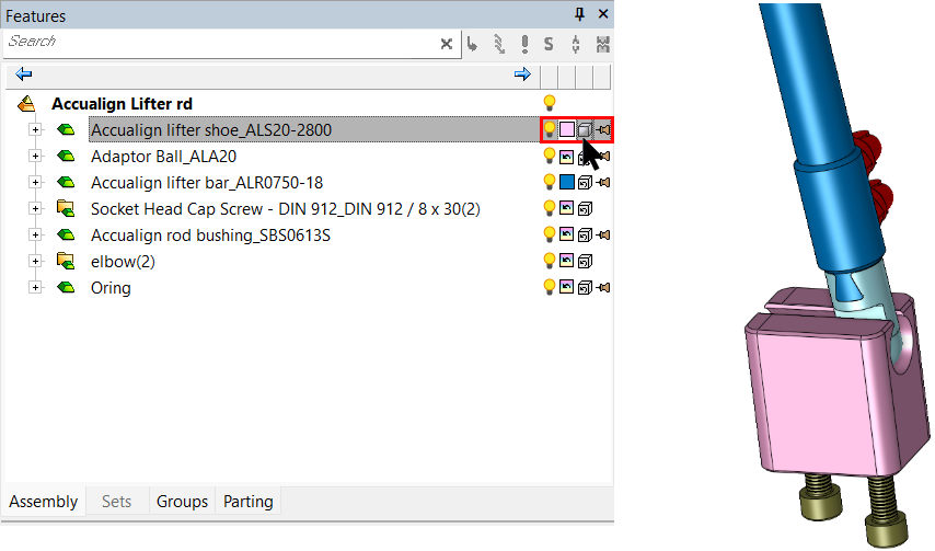
Color 

The colors of individual components in an assembly can be changed from within the Assembly Tree.
In a new assembly, all components are displayed in their original colors (the colors that the components are displayed in the Part environment) with the Original Color icon appearing for each component in the Assembly Tree. This means that individual faces of a component may be displayed in a different color.
Note: To change the original color of a component, activate the component and then use the Color tool.
Changing the color of a component from within the Assembly Tree changes the whole component to the specified color and the appropriate color icon appears for that component in the Assembly Tree.
To reset the color of a component back to its original color (), right-click on the appropriate component and select Reset Color from the popup submenu.
See Reset Color and Render Mode.
Changing the color of a component from inside the Assembly Tree
-
Select the color icon of a component/folder.
-
The Color Picker is displayed. Pick a color.
-
The component/folder and color icon are displayed in the selected color.
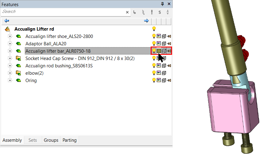
Render 


The render mode (shade / transparency / wireframe) of individual components in an assembly can be changed from within the Assembly Tree.
In a new assembly, all components are displayed using their original render mode (the mode that the components are displayed in the Part environment) indicated by the Original Render Mode icon which is displayed for each component in the Assembly Tree. This means that individual faces of a component may be displayed in a different render mode.
Notes:
-
To change the original render mode of a component, use either the Global or Local Render Modes.
-
The render mode of individual components can be controlled if the Global Mixed Render Mode is selected in the application menu.
Changing the render mode of a component from inside the Assembly Tree changes the whole component to the specified render mode and the appropriate icon (shade), (transparency), or (wireframe) appears for that component in the Assembly Tree.
To reset the render mode of a component back to its original mode () as it is defined within the component, right-click on the component in the Assembly Tree and select Reset Color and Render Mode from the popup submenu.
Changing the render mode of a component from within the Assembly Tree
-
Select the shade icon
.
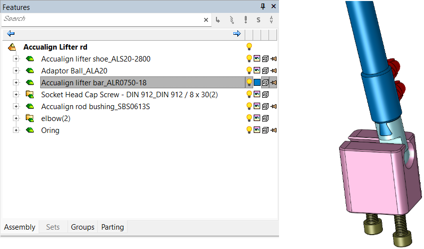
-
The transparency icon
is displayed and the component is shown is transparent form.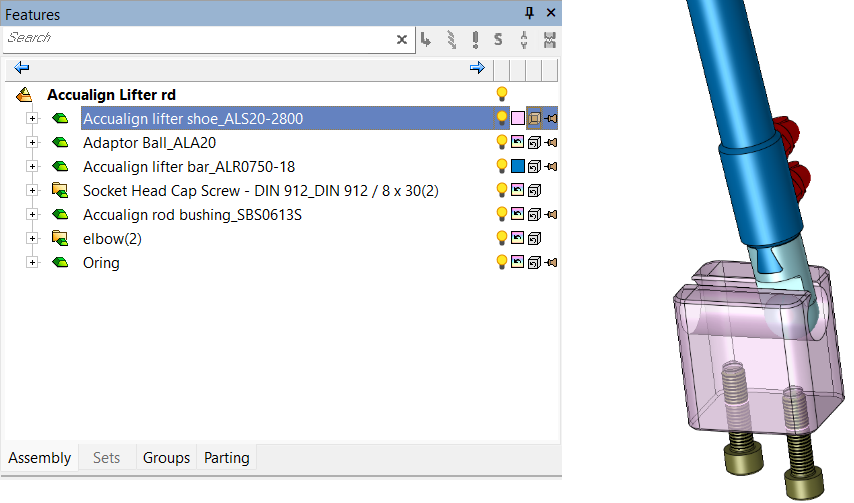
-
Click the icon again to display the wireframe icon
. The component is displayed in wireframe.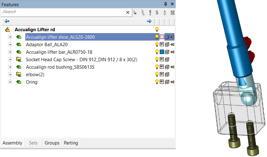
Fix / Float 

This icon determines the degrees of freedom for a component.
Fix all remaining degrees of freedom of a component in an assembly. The component is locked in its current position and cannot be moved. By default, when you add the first part to a new assembly the part position is fixed with the part origin coincident with the assembly origin.
Float a fixed component. The component regains the degrees of freedom it had prior to being locked.
Note: Fix / Float does not appear in the Parting Tree or Electrode Tree.