|
|
BOM: Report Assembly 
Creating a BOM report
Create a Bill of Materials (BoM) or Coordinate Table report by exporting the BoM or Coordinate Table to a file.
This option appears in the following dialogs in the Assembly and Drafting environments:
- Assembly: Assembly BoM Table.
- Drafting: Drafting BoM Table and the Drafting Coordinate Table Editor.
Click the ![]() button in the above mentioned dialogs to display the relevant dialog.
button in the above mentioned dialogs to display the relevant dialog.
- For the Assembly and Drafting BoM functions, this button exports the BoM to a file.
- For the Drafting Coordinate Table Editor function, this button exports the Coordinate table to a file.
In all cases, this displays the Export BOM to File dialog to save the relevant table as a file in the requested format. The Export BOM to File dialog differs slightly in the Assembly and Drafting environments.
Notes:
-
Some of the options displayed in the Assembly environment are not displayed in the Drafting environment; however, since the operations are very similar, all the options are described below, with Assembly specific parameters shown as such.
-
For Assembly BoMs, the type and name of the selected item (folder/sub-assembly) are exported to the report title. The report title also displays the type of filtering option used (if any) and if catalog components were excluded from the report.
The Export BOM to File dialog is displayed.
|
Assembly - Export BOM to File dialog: |
Drafting - Export BOM to File dialog: |
|
|
|
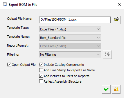
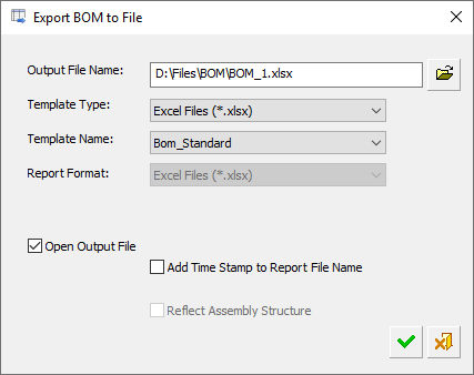
Parameters
|
Output File Name |
Set the name and path of the output file. The default file names and save locations for Assembly and Drafting BoMs are detailed below. These names and locations can be changed for each report. For Assembly BoMs:
For Drafting BoMs and Coordinate Tables: The default file name is that of the current file, however the name for each report can be edited. The default save location is that of the folder of the current file, however the save location can be changed using the adjacent Browse button.
|
||||||
|
Template Type |
Select a report template type from the dropdown list:
The Multi Format (*.repx) is the default format for report types that have not previously been saved. If this option is selected, the Report Format field (below) is available for selection. The last used save type is used for the next save. See the File Format Information for Reports, at the end of this Help topic. |
||||||
|
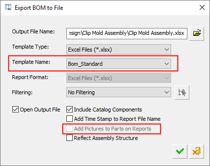
Template Name |
Select an Excel template from the dropdown list; the Template field in this dialog is only available if the file type is Excel. The default template and path is as follows:
For BOMs (Assembly and Drafting):
|
||||||
|
Report Format |
The Report Format field is only available if the Multi Format (*.repx) format is selected for the Template Type (above). Otherwise, it is dimmed and shows the option displayed for the Template Type. Select the report format from the dropdown list:
If the Report Viewer option is selected, the Open Output File checkbox is turned ON See the File Format Information for Reports, at the end of this Help topic. |
||||||
|
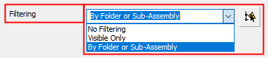
Filtering |
Displayed only in the Assembly Environment. Control which items are shown in the BOM report. The following filtering options are available:
|
||||||
|
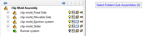
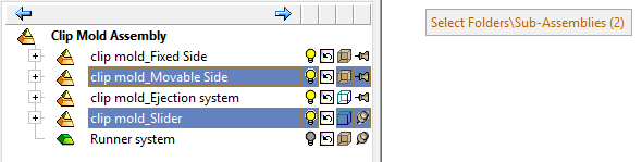
By Folder or Sub-Assembly |
Select one or more folders or sub-assemblies that will define the contents to be included in the BOM and filter out any part that is not in them. When the By Folder or Sub-Assembly option is selected, the When in folder/sub-assembly selection mode, the Select Folders/Sub-Assemblies (0) prompt is displayed.
The counter is incremented as folder/sub-assemblies are selected.
Either double click a single folder/sub-assembly to select it, or select multiple folders and/or sub-assemblies using the CTRL keyboard button and then <exit><exit> in the graphics window at the end of the selection. If a one selected item includes another, only the top item is considered. When exporting a BOM of a sub-assembly, if you select a folder or sub-assembly that is in a higher level than the active sub-assembly, a warning message is displayed and returns to the Export BOM to File dialog; in this case the Filtering option reverts to No Filtering. After selecting a folder or sub-assembly, the following occurs:
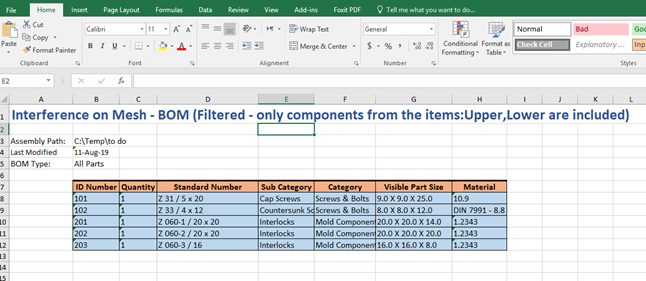
In the example below, Upper and Lower sub-assemblies are selected.
The resultant BOM report filters out all other parts.
|
||||||
|
Open Output File |
When this checkbox is marked |
||||||
|
Include Catalog Components |
Displayed only in the Assembly Environment. When this checkbox is marked |
||||||
|
Add Time Stamp to Report File Name |
When this checkbox is marked The default format of the time stamp is from the Preference setting. |
||||||
|
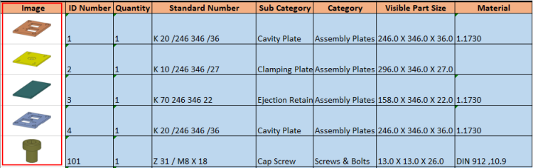
Add Pictures to Parts on Reports |
Displayed only in the Assembly Environment and is only available (not grayed out) if the selected template has an Image column. When this checkbox is marked
BOM showing pictures or parts in an Image column.
|
||||||
|
Reflect Assembly Structure |
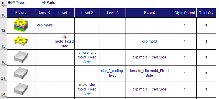
When this checkbox is marked This functionality allows viewing the assembly structure in the BOM report (in an Excel format for example), while getting all of the BOM information. The names of the columns are Level 0, Level 1, Level 2, etc. Each item goes into the relevant column in the same order as in the assembly.
If the Add Pictures to Parts on Reports option is selected, pictures are also added. If only specific folders or sub-assemblies were selected, or the Visible Only filter is used, the table starts from the common parent of all selected items. The Reflect Assembly Structure option is only available if the All Parts option is selected for the BOM. |


File Format Information for Reports
Definitions of the available report file format templates are listed below. The last used save type is retained for the next save.
-
3D PDF File (*.pdf) – Adobe Portable Document Format (PDF). 3D PDF files include parts and assemblies from Cimatron. These interactive 3D PDF files look exactly like the original 3D design and enables users to view, package, and share 3D design data. Operations such as zoom, pan, and rotate, plus additional extended tool operations can be performed on the models in the 3D PDF files. The free Adobe Reader is required to view PDF files. Download the latest version of Adobe Reader from Adobe's website (https://www.adobe.com).
-
CSV File (*.csv) – Comma-Separated Values (CSV). CSV files are used to store tabular data (numbers and text) in plain text. Files in the CSV format can be imported to and exported from programs that store data in tables. Each line of the file is a data record. Each record consists of one or more fields separated by commas.
-
Excel 97-2003 File (*.xls) – Microsoft Excel 97- Excel 2003 Workbook. This format can be viewed using a free viewer from Microsoft and does not require an Office installation on the client machine to create a report. However, to edit data, save a workbook, or create a new workbook, this format requires that Microsoft Office be installed on the client computer.
-
Excel File (*.xlsx) – Microsoft Excel Workbook. This format can be viewed using a free viewer from Microsoft and does not require an Office installation on the client machine to create a report.
-
Excel File with Macro (*.xlsm) – Microsoft Excel Macro-Enabled Workbook. This format can be viewed using a free viewer from Microsoft and does not require an Office installation on the client machine to create a report.
-
Multi Format (*.repx) – Report Preview. This format allows you to preview the report before creating a report in one of the other supported formats. This is the default format for report types that have not previously been saved.
-
PDF File (*.pdf) – Abode Portable Document Format (PDF). The free Adobe Reader is required to view PDF files. Download the latest version of Adobe Reader from Adobe's website (https://www.adobe.com).
-
Single File Web Page (*.mht) – Microsoft embedded HTML format file. This web page archive format is similar to an HTML file where all images and linked files are saved, along with the HTML code, into a single file. This format can be viewed with Microsoft Internet Explorer or Microsoft Office (as well as other software).
-
Text File (*.txt) – Creates a text in Microsoft Notepad.
-
XML File (*.xml) – Extensible Markup Language (XML). This format stores data that can be read by other programs. XML is similar but distinct from HTML. XML is for carrying data while HTML is for displaying it.
|