Cooling Objects  : Options and Results


Access: Open this function from one of the following locations:
-
Select Mold Design > Cooling > Cooling Objects from the menu bar.
-
Select Cooling > Cooling Objects from the Mold Design Guide Toolbar.
Create an object that will define the holes that will be created around the cooling lines.
Create the cooling channels around the sketched lines, with or without the cutting operation between the cooling objects and the mold plates. If the Without Cut option is used, the cutting operation can be achieved manually by using the Cooling Cut function.
Important: Make sure that the required assembly is activated before using this operation.
Required Step 1 
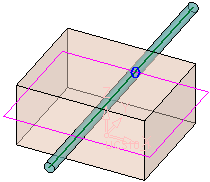
Pick a cooling sketch or contour from which the cooling channels will be created. Composite curves can also be selected.
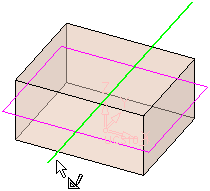
Note: Only straight lines can be considered as the channel axes.
Required Step 2 
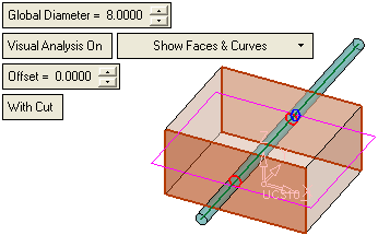
Define the cooling channel parameters.
|
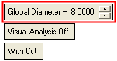
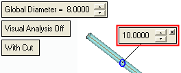
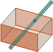
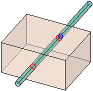
Global Diameter |
You can either set the Global Diameter of all the channels or set the diameter of an individual channel by picking the blue circle in the middle of the channel and entering the diameter in the popup.
|
|||||||||||||||||||||
|
This is a toggle option Visual Analysis Off / Visual Analysis On that enables you to check the proximity of the cooling channel to other components (faces, screws, holes, etc.). When toggled to ON, a component that touches a cooling channel is displayed in red.
When the Visual Analysis parameter is toggled to On, additional parameters are displayed. Visual Analysis On parameters:Visual Analysis On parameters:
Notes:
|
||||||||||||||||||||||
|
With Cut / Without Cut |
Set the With Cut / Without Cut toggle option. When using the option With Cut, the following occurs:
|
Optional Step 1 
Set the drilling parameters.
|
Drill Extension |
This is a toggle option that enables you to define a drill extension and its length. The toggle options are Drill Extension / No Drill Extension. See Drill Extension below for a detailed description of this parameter. |
|
Drilled End |
This is a dropdown list of options that enables you to define the type of channel tip to be displayed at channel ends. See Drilled End below for a detailed description of this parameter. |
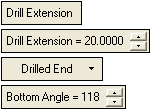
Drill Extension
This is a toggle option that enables you to define a drill extension and its length. The toggle options are Drill Extension / No Drill Extension.
|
Drill Extension |
Create drill extensions. The drill extension length can either be set globally for all the channels or you can set the drill extension length of an individual channel by picking the appropriate blue X and entering the length and, if required, channel tip type, in the displayed parameter label. Drill extension - globalDrill extension - global Drill extensions of the same length To define a global drill extension:
Note: Global drill extensions will only affect those extensions whose lengths have not been individually defined.
Drill extension - localDrill extension - local Drill extensions of varying lengths To define drill extensions of varying lengths:
Notes:
|
|
No Drill Extension |
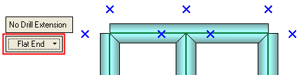
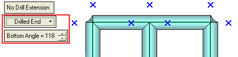
Do not create drill extensions.
If the drilling extension is not created, check if the channel is feasible i.e. it can be drilled. |
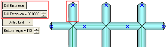
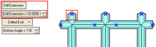
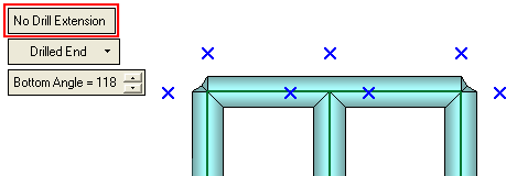
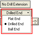
Drilled End
This is a dropdown list of options that enables you to define the type of channel tip to be displayed at channel ends.
Notes:
-
All channel intersections can have a type of end tip defined.
-
Only the channel lines that end within the object to be cut can have a type of end tip defined.
The following options are available:
|
Flat End |
All the channels endings are flat shaped.
|
|
Drilled End |
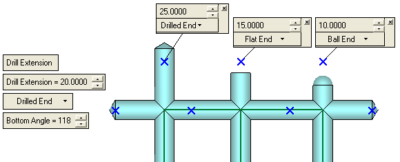
All the channels endings are drilled end. This is the default option. In this case an additional parameter is displayed - Bottom Angle. Set the Bottom Angle to define the tip shape.
|
|
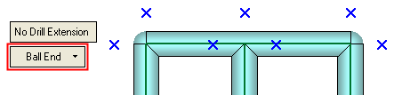
Ball End |
All the channels endings are ball shaped.
|
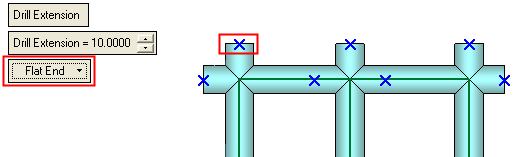
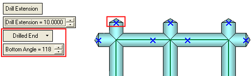
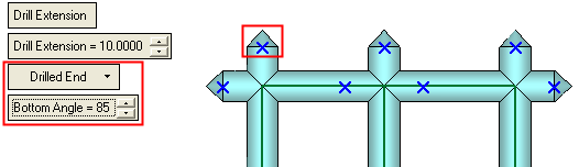
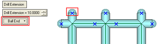
The channel tip type can either be set globally (as shown above) or you can set the type of tip for an individual channel by picking the appropriate blue X and entering channel tip type and, if required, the extension length, in the displayed parameter label.
Note: The different types of channel tips can also be defined even if No Drill Extension is set.
ExamplesExamples:
Optional Step 2 
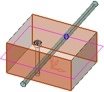
The Cut Manager is displayed; select the parts to be cut. This step enables you to manually control which parts are to be cut.
All the parts that are going to be cut by the cooling objects (according to the cooling cut analysis) are displayed in the Cut Manager dialog.
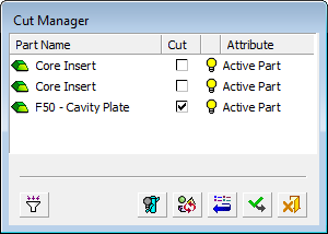
The list inside the dialog includes all parts intersected by the bounding box of the cooling object, an example of which is shown below:
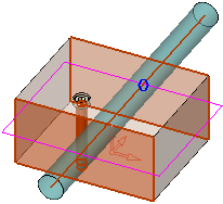
The various parts are then checked according to the detailed cut analysis and filter definitions. Only parts that are going to be cut (according to cooling cut analysis) are shown (they have the "show" attribute in the Cut Manager). For example:
Press OK ![]() or Apply
or Apply ![]() in the Feature Guide to complete the function.
in the Feature Guide to complete the function.
The following occurs:
-
Depending on the With/Without Cut option selected:
With Cut
The selected parts are cut by the cooling objects and, if required, the cooling items.Without Cut
-
If With Cut is selected, the new faces created by the cut operation are given a color defined in the Preferences.
-
The faces of the cooling channels are grouped in a set called Cooling Faces. There is only one set by this name and for subsequent cut operations, the new faces are added to the existing set.
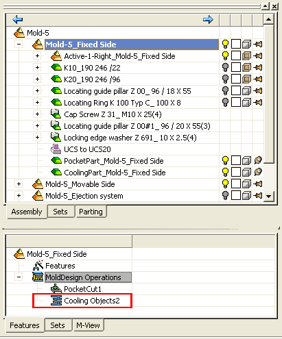
When completed, the Cooling Objects feature will appear in the Feature Tree as follows:
Notes:
-
The system cuts all the plates in the active assembly that the cooling channels pass through.
-
The cooling channel object in the cooling part is hidden, by default. To display it, activate the cooling part and show the cooling object.
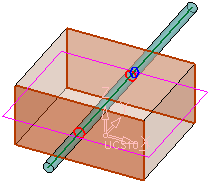
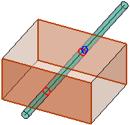
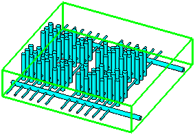
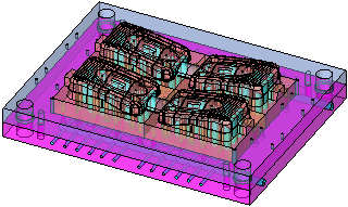
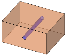
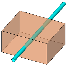
Below is an example of the result of the Cooling Objects operation.