Exploded View

Access: In the Tree Pane click the M-View tab, right-click and select New Exploded view.
Cimatron enables users to create exploded views from all assembly type models. Exploded Views are used for demonstration, marketing, and documentation purposes, enabling users to learn the assembly procedure of molds.
While creating exploded views, you can edit hierarchies at any time by clicking the Edit Hierarchy button in the Feature Guide, as described in Exploded Views - Advanced Options.
|
Demo: Press the button below to view a short movie demonstrating the function. |
|
|

Note: Exploded views are enabled for assembly files only.
Creating an exploded view
Select the assembly model from which you want to create an Exploded View. It is recommended that you hide all the components in the Assembly Tree apart from Fixed Side and begin creating your exploded view for the fixed side, then proceeding with the other sides (as shown in the example below).
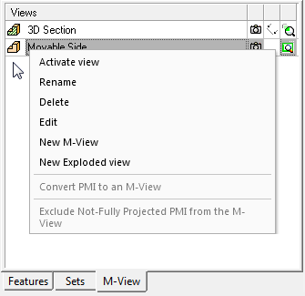
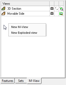
Right-click the M-View tab (either on an existing M-View or in an empty area) and select New Exploded view from the popup menu.
|
Popup on selected M-View |
Popup on empty area |
|
|
|
The Exploded View Feature Guide and parameters are displayed.
General Interaction
The following is the Feature Guide for Exploded View.
Required Step 1 ![]() : Pick the components to be exploded.
: Pick the components to be exploded.
Optional Step 1  : Edit the Parent/Child Hierarchy (see Exploded Views: Advanced Options).
Required Step 1 
Pick the components to be exploded and locate them by pressing Auto Explode or by dragging the direction arrow. The following parameters are displayed:
|
|
|

Parameters
|
<Exploded View Name> |
The name of the exploded view. Click this screen parameter to enter a new name. |
||||
|
Auto Explode |
Automatically explode the view of the selected components. To clear the display of the components in 'selected' mode, press the Clear Selection parameter (see below).
|
||||
|
Delta |
Define the distance between the components in the exploded view and then select all the components. |
||||
|
<- -> |
Use the arrow buttons to move the selected components by the Delta distance in the defined direction. To set a direction and to see another method of moving the selected components, see Dragging the Components below. |
||||
|
Reset |
Place the exploded components in their original locations. |
||||
|
Hierarchic Selection / |
This is a toggle option that enables you to either pick a component and have automatic selection of hierarchically connected components or to simply pick a component with no automatic selection of hierarchically connected components.
Note: The Hierarchic Selection option is used for moving groups of connected components as one entity. |
||||
|
Clear Selection |
Clear the display of the components in 'selected' mode.
Note: The BLUE dash lines indicate the direction of movement of the components. The RED circles are used to break the explode lines. |
||||
|
Hide Lines / |
This is a toggle option that enables you to either hide or show the exploding lines.
|
Note: You can press Clear Selection at any time to clear the selection and select different components. In addition, you can select Reset to place the components in their original locations.
Dragging the Components
Click an arrow and drag the components in the direction of the arrow.
|
Click and drag |
To set a direction, click the BLUE point in the center of the arrow. The arrow popup menu is displayed enabling you to select the required direction. |
Optional Step 1
Edit the Parent/Child Hierarchy (see Exploded Views: Advanced Options).
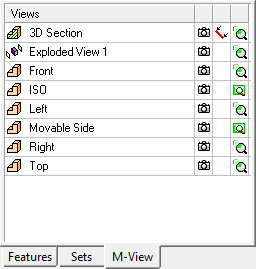
Click OK ![]() in the Feature Guide. The exploded view that you created is displayed in the M-View tab with the Exploded View icon
in the Feature Guide. The exploded view that you created is displayed in the M-View tab with the Exploded View icon ![]() .
.
You can now perform additional advanced options to the exploded view (as described in Exploded Views - Advanced Options) and then repeat the steps above to create exploded views for the other sides. In addition, you can create drafting views from exploded views (as described in Creating a D-View).