|
|
2D Drawing Toolset Overview
General
The 2D Drawing Toolset allows you to manipulate view geometry as well as add 2D geometry to existing views. Most of the 2D Drawing functions available in the Part environment can be used in Drafting with certain enhancements and some limitations.
In order to work with a view, it must be activated. This is done by either picking the view and selecting Activate view from the right-click popup submenu, or by selecting the view name in the Drawing Tree and selecting Activate view from the right-click popup submenu. The activated view is highlighted for clarity.
The display parameters for the activated Sheet, View and Frame are defined in the Preferences Editor.
Drafting View geometry can be automatically referenced when applying most 2D Drawing Toolset functions. Functions that are not automatically referenced on the view include, Move, Copy, Rotate and Mirror.
For a detailed description of the Sketcher function, see Sketcher.
2D Geometry Dimensioning
Dimensions can be added to 2D geometry associated with the active object. It is possible to edit the values of linear, radial and angular dimensions during creation. Thereafter, they are treated as regular drafting dimensions.
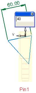
In the following example, a linear dimension is applied to the 2D geometry (dimmed) of an active view.
To dimension 2D geometry:
-
Click the Dimension button
 on the 2D Drawing Toolset toolbar.
 -
Pick the entity to be dimensioned:

-
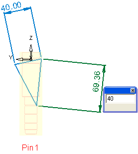
Click in the graphic area to position the dimension, edit its value and <exit><exit>:

The geometry updates automatically:

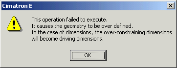
Note: If we try to change the dimension value of a constrained line, an error message will be displayed. In the example below the picked line is constrained by origin and end points on the active view:


|