Datum Target 

Access: Open this function from one of the following locations:
-
Click the
button in the toolbar. -
Select Symbols > GD&T > Datum Target from the menu bar.
Add a Datum Target symbol to the drawing.
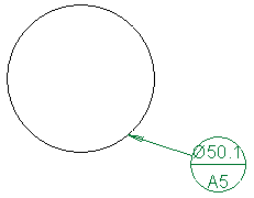
Datum Target is a specified point, line, or area on a part that is used to establish the Datum Reference Plane for manufacturing and inspection operations.
|
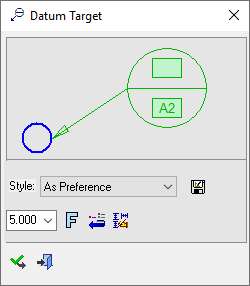
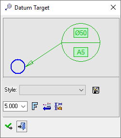
The Datum Target dialog displays |
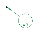
Below is an example of the symbol: |
|
|
See Entity Overview for a general description. |

Edit or re-position a symbol after creation
Double-click the appropriate symbol. The relevant dialog associated with the symbol is displayed. This means that you are now in edit mode.
Edit the symbol elements and/or re-position the symbol as required.
The procedure below describes how to create this symbol in Cimatron.
Creating a Datum Target symbol
-
InvokeInvoke the Datum Target function.
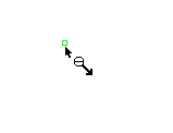
The Datum Target dialog is displayed and the cursor changes, as follows:  .
.
-
Pick a symbol location or leader position. Picking an unattached point will first place the symbol and then the leader. Picking an attached point will place the leader first and the second pick will place the symbol. The following is displayed:
Picking an unattached point
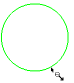
Picking an attached point:
-
Edit its parameters with the help of the hot spots and tips either directly in the graphic area or on the popup submenu. When applied to a circle or arc, the diameter appears in the Upper Text field. You can change the font style
 and character size, if required.
 -
To complete the current operation and remain in the dialog, click the Apply
 button or <exit><exit>.
To exit the function, click the Close button.
Notes:
-
Right-click the entity itself to access the entity-specific (for editing) and general functions from the popup submenu.
-
Double-click the entity to edit it.
-
Creating a PMI datum target symbol (in the Modeling environment) is very similar to creating a datum target symbol in the Drafting environment, even though modeling is a 3D environment and drawing is a 2D environment.
-
See the Symbol notes for additional information.