Tool Axis Control
Tilting strategy
Automatic Tool Axis Control Option
The feature adds a new mode called Automatic to the tool axis control. The contact point and the lead/lag angles are automatically defined according to each available tool.
The advantages of this option are:
- Reduced programming time
- Simplified tool axis definition.

User Defined Tool Axis Control Option
In this mode the user has the posibility to define the contact point and lead angle values.
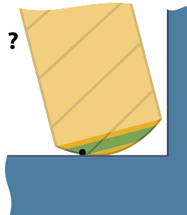
Relative contact point height on tool profile
Preferred
The preferred contact point is calculated to ensure the tool is aligned tangentially at the specified contact point on the surface.
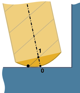
Minimal
The minimal contact point height defines the minimal height that the contact point can have when the tool is tilted to avoid collisions.

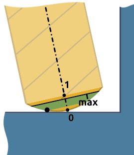
Maximal
The maximal contact point height defines the maximal height that the contact point can have when the tool is tilted to avoid collisions.
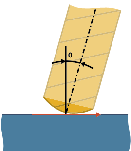
Lead angle relative to surface normal
Preferred
An additional lead angle can be set. The preferred lead angle is defined as the angle between the tool axis and the plane with the feed vector as the plane normal.
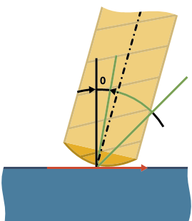
Minimal
The minimal lead angle is maintained when the tool is tilted to avoid collisions.
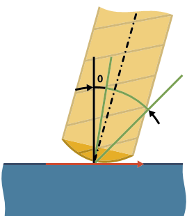
Maximal
The maximal lead angle is maintained when the tool is tilted to avoid collisions.
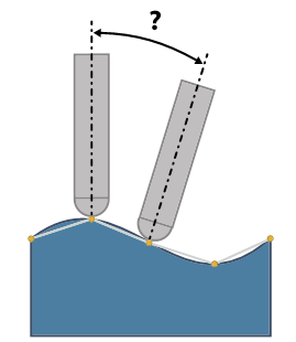
Max. angle step
This option sets the maximum allowed angle change between two consecutive toolpath positions. The calculation engine outputs 5-axis toolpath data that contains the tool tip position and the direction vector of the tool. The direction vectors must not have an angle change more than the value specified here.
This option also defines the resolution of the maps used for collision checking. That means that collisions are checked every 3 degrees (angle change of the tool axis). A 3 degree step angle is usually enough, depending on the model geometry and the tool geometry. If there are sections along the contour where the tool is very close to the geometry, a 3 degree step might be too large to find a solution and a finer resolution should be used (2 degrees, 1 degree or even smaller).
This parameter has a big impact on the computing speed and can cause a failure if there are sections where the solution exists only for a couple of degrees in the orientation of the tool.
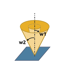
Tilt Limits
This option limits the tool between two angles starting from the toolpath slice normal vector. For example, imagine 2 cones with different opening angles w1 and w2. The tool axis direction is enforced to be between these 2 cones. The orientation of the cones depends on the cone axis settings. You can set the orientation to the x, y and z directions as well as to a user defined direction.