Roughing - Advanced
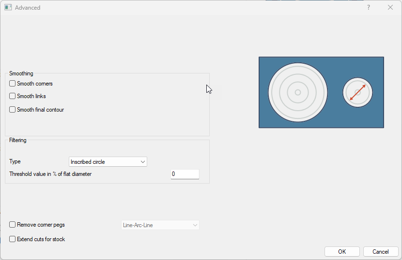
Smoothing
|
Item |
Description |
|
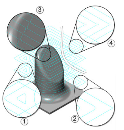
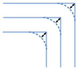
Smooth corners (1): |
The smooth corners will create fillets in the sharp corners of the toolpath. Note that the fillet will not be applied to the outer contour. For the fillet to be applied to the outer contour, the user would have to use 'Smooth final contour'. |
|
Smooth final contour (2) |
The smooth final contour will create fillets in the sharp corners of the outer contour. The radius of the fillet is to be entered as a percentage of the step over distance. |
|
Smooth links (3): |
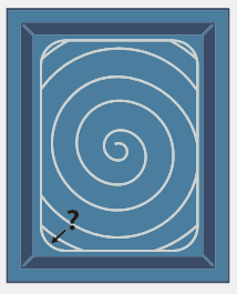
This will smooth the links within a group. The last segments of the previous contour and the first segments of the next contour will be trimmed. The connecting link will connect diagonally. In cases where there is a blend spline linking, the connection would be defined as an 's' type link. |
|
With a step over greater than 50% of the tool diameter, small pegs of material may be left in the corners. This option will automatically modify the actual step over value, and add extra cuts to the corners, in order to remove uncut material. The remove corner pegs feature cannot be applied when the modified step over is less than 5% of the tool diameter. This occurs when the tool has a small flat cutting area. |
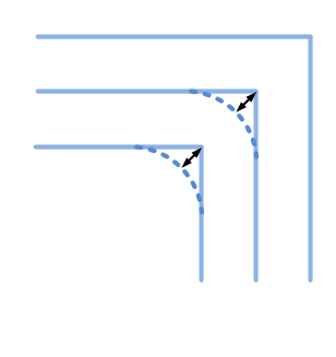
Smooth distance (stepover %)
The smooth distance is the value for the amount of smoothing. This is measured from the original contour and the rounded corner. The smooth distance for the final contour works in the same way, but this value is only valid for the final contour.
Smooth link gap size (stepover %)
This allows the user to control the smoothness of the Blend spline link between neighbor cuts within a group. It is defined as a distance between the start and end points of adjacent cuts within a group.
Notes:
- This is only available for the Offset roughing type.
- This is only available once the Smooth links option has been activated.
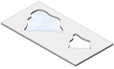
Filtering
This allows the user to remove toolpath regions based on their size. If the width of a toolpath region is less than or equal to the specified threshold, this region will be filtered out.
This is useful to avoid the machining of unnecessary areas.
Two types of filtering are available:
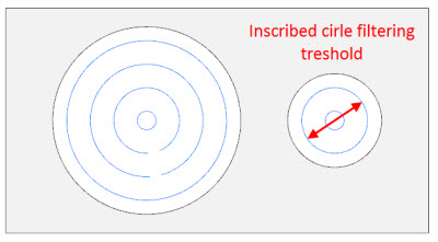
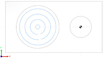
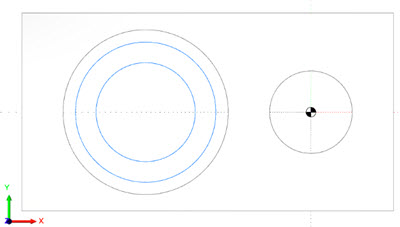
- Inscribed circle: the width of the region is a maximum circle diameter, which could be inscribed into the toolpath within this region. See the two upper images.
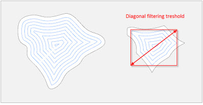
- Diagonal length: the width of the region is a diagonal of the axis-aligned bounding box built around the toolpath within this region. See the two bottom images.
The threshold is a percentage of the tool diameter.
Filter by: regions, contours. This defines which part of the toolpath could be filtered out. This could be the entire region or a certain contour.
This picture shows the result where the filter by Region type has been performed.
This picture shows the result where the filter by Contour type has been performed.
Extend cuts for stock
This option enables the user to extend the morph toolpath to the top of the stock material in case it is located higher than the ceiling surfaces.
This is available for the Multiaxis Roughing Morph and Offset from Ceiling strategies.
Dependent desired stepover
This option lets you avoid the hardcoded dependency between the maximum and desired stepovers in the adaptive roughing pattern. The desired stepover parameter can take any value which is less than the maximum one. The hardcoded value is 1.25 x maximum stepover.
Available for Adaptive type only.
Minimal curvature radius
This parameter improves cutting conditions in corners and slots in the adaptive roughing toolpath. The option has been designed for making the toolpath smooth enough while maintaining the majority of moves with a curvature radius greater than the given value. It is useful for getting rid of tiny slots.
Available for the Adaptive type only.
Break through overlap
This option enables users to specify an additional machining area that requires processing after the tool has broken through the thin wall of stock material.
This usually occurs at the end of slots machining. This feature makes the exit safer without instantly going through the thin walls.
This option is only available for the adaptive roughing type.