|
|
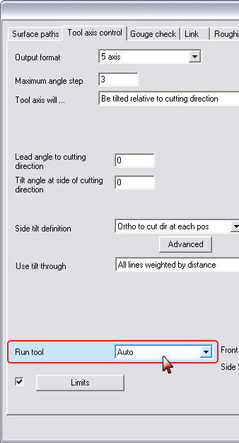
Check
This parameter defines the contact point of tool and drive surfaces. Optional settings:
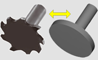
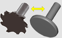
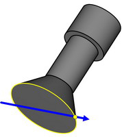
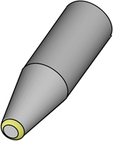
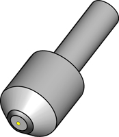
- AutoAuto
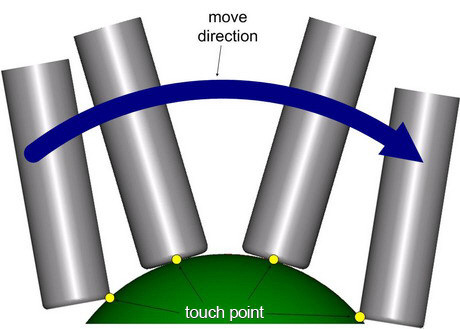
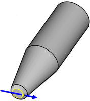
The 'Auto' option is the automatic mode. So the system decides where the tool shall touch the surface.
If the user changes the orientation of the tool, then the surface contact point remains and the contact point on the tool moves from the tip of the tool to the radius of the tool still maintaining the tangency between tool and surface.
In this example the tool axis limit angle is 70 degree. Now if the tool machines under this limit the system chooses run tool option 'center'. When the tool comes to the limited areas the touch point changes to the tool radius.
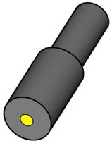
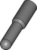
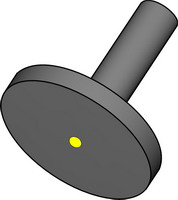
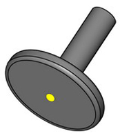
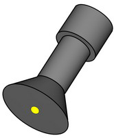
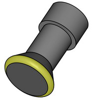
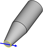
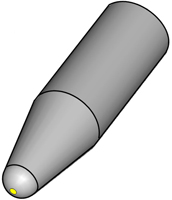
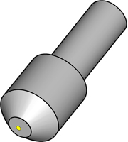
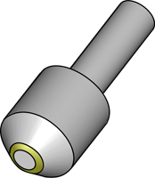
- CenterCenter
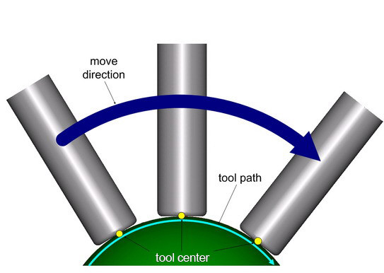
If this parameter is set to 'Center', then the tip of tool is touching the surface contact point. If the tool axis orientation is changed due to tilting options, then the tool will be tilted around this tip point. In such case, the tool and surface are not tangential anymore and tool will gouge the surface. This must be then avoided by explicitly turning on gouge checking and setting the first gouge check strategy to retract back the tool from drive surfaces.
Here you can see the tool touching the surface always at the center.
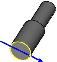
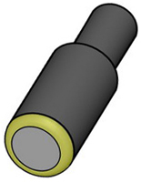
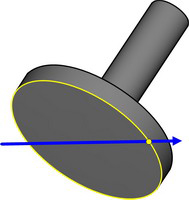
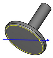
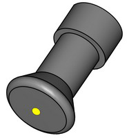
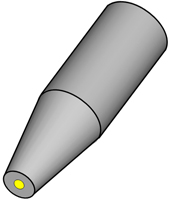
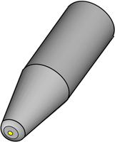
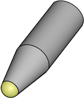
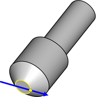
- FrontFront
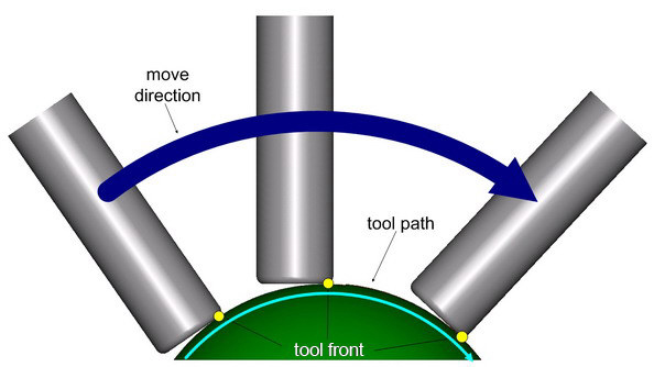
The option 'Front' is similar to 'Center' and forces the tool touching point to be always a fixed point on the tool. All changes to tool orientation are done around this pivot point and this will also cause gouging the drive surfaces. Setting the gouge control is critical to work with this option.
Here you can see the tool touching the surface always with the front
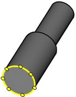
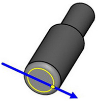
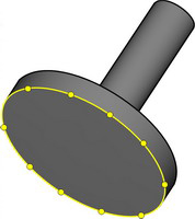
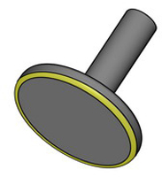
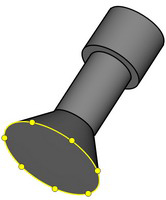
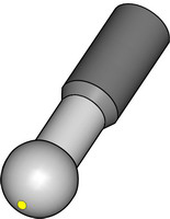
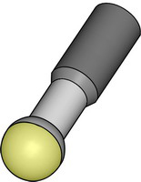
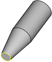
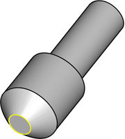
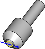
- RadiusRadius
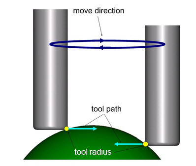
If this parameter is set to 'Radius', then the tangency is maintained like in the case of 'Auto', the difference is that for a bull nose tool, the tip of the tool is used as touch point on the drive surfaces.
In this example you can see a bull mill machining around the sphere. It doesn’t matter on which position the tool is, the touch point is always at the radius.
- User given point
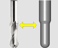
Tool area definitions
|
Tool |
Center |
Radius |
Front |
|
|
Flat end mill
|
|
|
|
|
|
Sphere end mill
|
|
|
|
|
|
Bull end mill |
|
|
|
|
|
Slot mill no radius
|
|
|
|
|
|
Slot mill corner radius
|
|
|
|
|
|
Dove mill no radius
|
|
|
|
|
|
Dove mill with corner radius
|
|
|
|
|
|
Lollipop mill |
|
|
|
|
|
Taper mill without corner radius |
|
|
|
|
|
Taper mill with corner radius |
|
|
|
|
|
Taper mill with full radius |
|
|
|
|
|
Chamfer mill without radius
|
|
|
|
|
|
Chamfer mill corner |
|
|
|


Notes:
-
The dimensions of the tool are set up in the tool parameters.
-
Additional to the tool basis dimensions clearance distances can be added
|
Choose the run tool option from the drop down menu. |
|
|