Extract by Contour 


Access: Open this function from the following location:
-
Select Assembly > Tools > Extract by Contour from the menu bar.
Extract geometry to a separate file by defining a contour containing the required geometry.
This function is useful for creating insert parts automatically by defining a 2D contour. The 3D geometry inside a contour you select will be removed from one part and added to a new part in the assembly, within a pocket created where the 2D contour was drawn. This function is useful for both mold and die makers.
The inserts are created by picking a component and then picking the contours that are used to create the inserts.
|
|
In this image. a 2D contour is selected around the geometry of the required insert and the insert is automatically created based on the 3D geometry of the component. |
Using Extract by Contour
This image shows the Feature Guide for Extract by Contour.
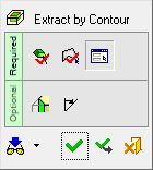
Required Step 1 ![]()
Pick the component from which the required geometry (insert) will be created.
Required Step 2 ![]()
Pick the contours that define the shape of the new geometry (insert). The component selected in required step 1 is divided by these contours.
Required Step 3 ![]()
Pick a target assembly and set the insert parameters and names. The new insert is imported into a new part created in the selected assembly.
Optional Step 1 ![]()
Create chamfers on all the selected side edges of the insert(s) and create corners on all the selected side edges of the resulting pocket(s).
Optional Step 2 ![]()
Create draft angles on the insert(s) and the resulting pocket(s).
Detailed Interaction
See Options and Results.