|
|
Feature Recognition
Filter or set which geometries to be detected by the algorithm by specifying the kind of contour that the system will use.
Click the following image to go to the descriptions.
- Make your selections using the parameters detailed below.
- Click the Confirm buttonConfirm button
 or Cancel buttonCancel button
 .
.
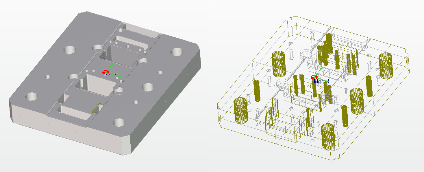
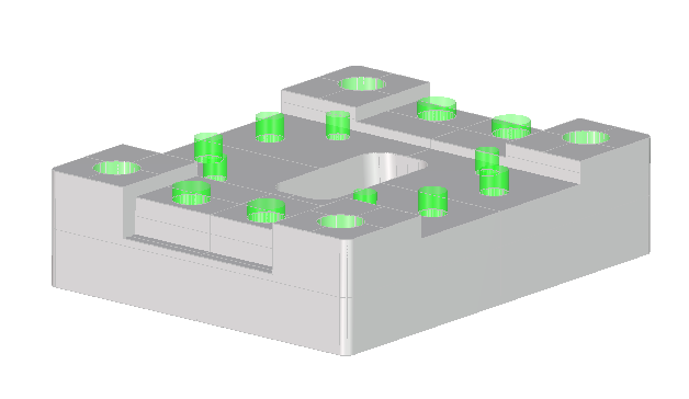
After selecting the geometry is necessary to confirm the selection. The following image shows all the features recognized by the system.
Select all and Un-select all
|
Button |
Function |
Description |
|
|
Select all |
Select all options can be used to select all the options together to make Feature Recognition |
|
|
Un-select all |
Deselect all options to select only the features required for Feature Recognition |


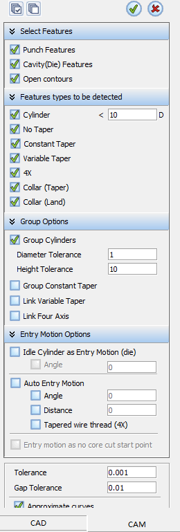
Select Features
Filter or set which geometries the algorithm will detect using that kind of contour.
-
Punch Features: Outside contour of the part
-
Cavity (Die) Features: Inside contour of the part
-
Cavity Features: Contour that has an open face
Features types to be detected
Filter or set which geometries the algorithm will detect using that kind of features type.
-
Cylinder with less than Diameter: Filters the maximum diameters the system will accept in the algorithm, and selects the smaller specified diameter
-
No Taper: 2X profiles that do not contain any taper
-
Constant Taper: Same taper angle (for all sides)
-
Variable Taper: Different taper angle
-
4X: Which have multiple sides with different angles
-
Collar (Tapper): Height of the taper profile
-
Collar (Land): Height of the Land profile
Group Options
This panel helps the user to group the wireable parts by groups to simplify the programming using the same cutting technology for all the parts.
- Group Cylinders: The Group Cylinders option is divided into two parts.
- The first will make a first classification of the cylinders in relation to their diameter.
- The second will group compatible cylinders in each set that was created in the first classification in relation to height and level, to be machined together.
-
Diameter Tolerance: While using the diameter tolerance with the specified value, the system tries to group the diameters according to this range.
For example, the system will analyze all the cylinders and try to group them using a specific tolerance inside this range. If the specific tolerance is 2mm, and there are several cylinders around 10mm, the system will group the diameters between 8 to 12 together.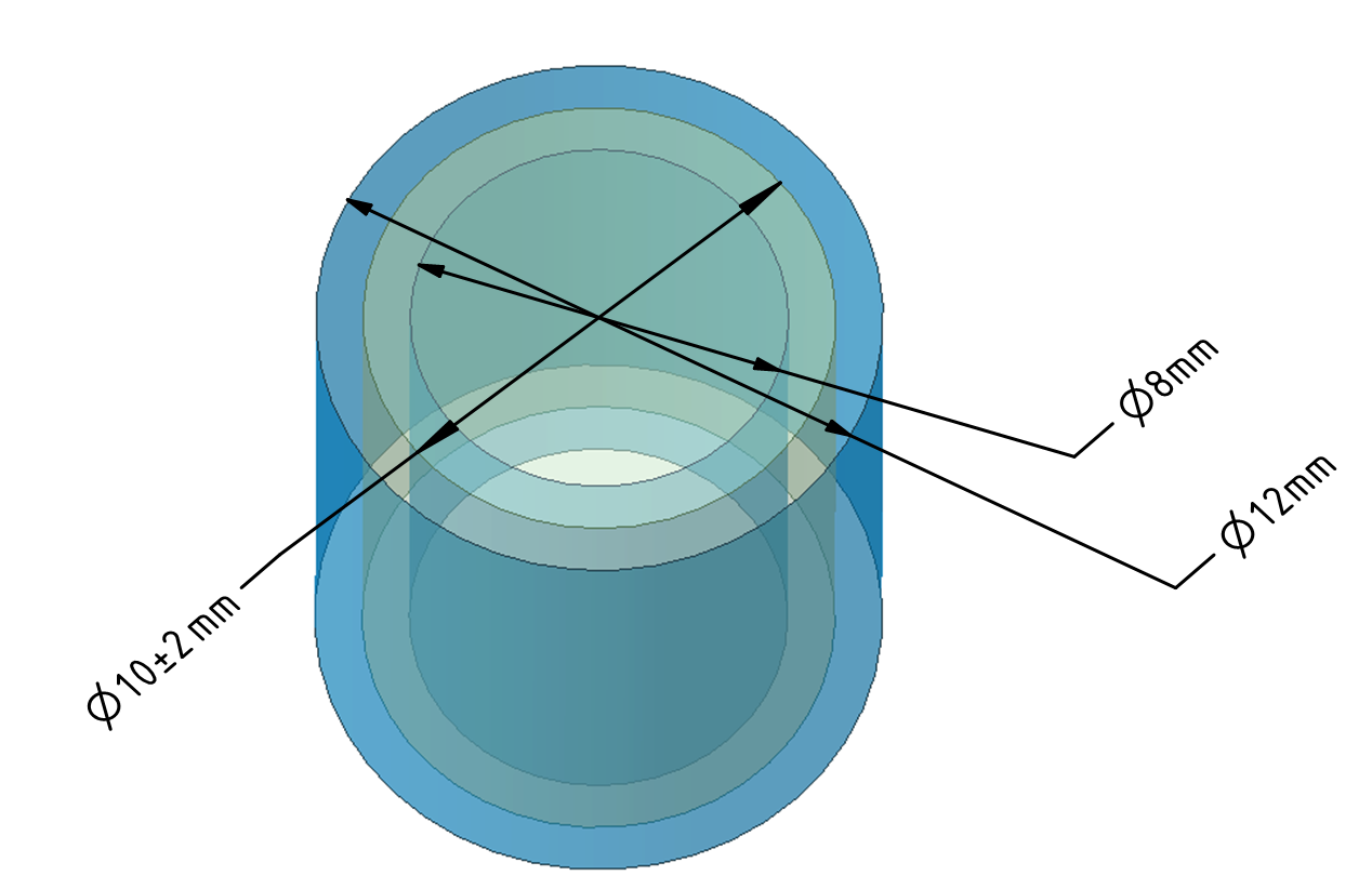
This image shows that there are different ranges of cylinder diameter that have to be grouped together with the specific tolerance to create technology.
In this case and due to the Tolerances, the system has created two groups containing all the cylinders:
-
First group with diameters from 5 to 12 mm
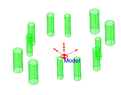
-
Second group with diameters of 15 mm.
-
-
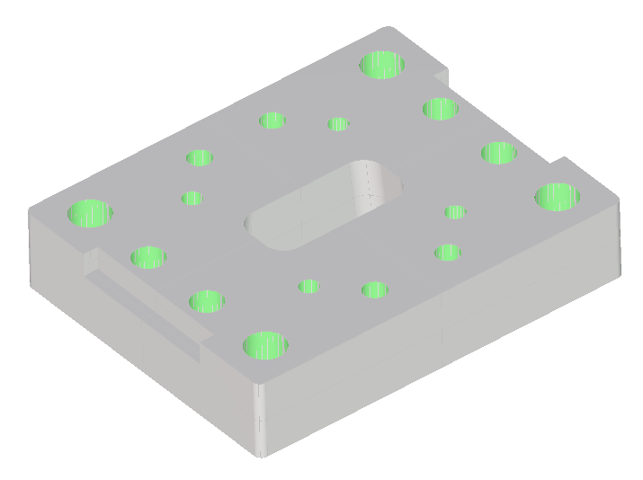
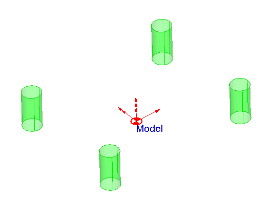
Height Tolerance: The height tolerance with the specified value detects the tolerance of the applied value.
For example, if the plate height is around 25mm, with faces at different levels such as 25mm, 22mm, and 20mm.
To apply the same process to the plates at these height differences, a height tolerance of 5mm will group the faces together to create technology for the same height.
This image shows that the profiles have different heights, and the component has been analysed using a height tolerance to create geometry that has the same height to define the same cutting technology for all profiles in the plate.
-
Group Constant Taper: Link variable taper geometries into one geometry
-
Link Variable Taper: Link variable taper geometries into one geometry
-
Link Four Axis: Link four axis geometries into one geometry
Entry Motion Option
Configure the wire entry for the parts to simplify the programming using the same cutting technology for all the parts.
-
Idle Cylinder as Entry Motion (Die): Entry motion will be considered as a specified wire entry hole.
-
Auto Entry Motion: Entry motion will be defined as per the geometry automatically.
-
Angle: Entry Motion will be defined as per the Angle specified with respect to Geometry.
-
Distance: Entry Motion will be defined as per the Distance specified with respect to Geometry.
-
Tapered wire thread (4X): The Wire Entry will be defined in the taper angle position with respect to Geometry.
-
Entry motion as no core cut start point: No core Cut as Entry motion will be applied for all the geometries automatically.
|