Fillet  : Options and Results


Access: Open this function from the following location:
-
Select Faces > Create Faces > Fillet from the menu bar.
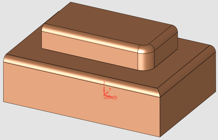
Create fillet faces between two (2) sets of smoothly connected faces. Each set may consist of one or more faces that may be trimmed or split as required. Sometimes it can be unneccessary to trim or split faces when performing a fillet operation, such as when one face will be needed later in separate face operations-The fillet operation provides that option.
The Fillet function allows you to create fillet faces with a Constant Radius or a Variable Radius. You can also trim the fillet faces, or split them if this will yield better results than trimming (for example, to develop a smooth binder that can be pulled off the part).
|
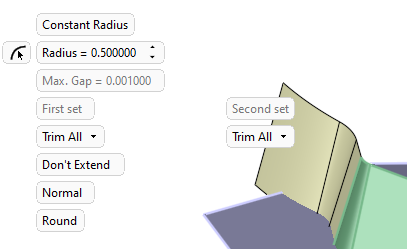
Constant Radius |
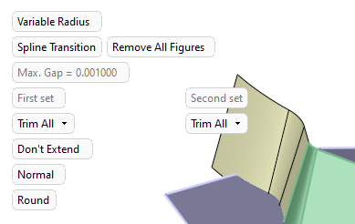
Variable Radius |
|
|
|
Examples
The following examples show the multiple ways Fillet can be used to produce the required results. The videos and practice files below are also helpful tools to understand and implement the Fillet function in your work environment.
|
Demo: Press the button below to view a short movie demonstrating the function: |
Practice: Press the button below to open Cimatron with a practice ELT file similar to that used to create the movie (if the relevant feature already exists in the ELT file, you can either edit it or delete it and create a new feature). |
|
Fillet > Constant Radius
|
|
|
Fillet > Variable Radius
|

Required Step 1 
-
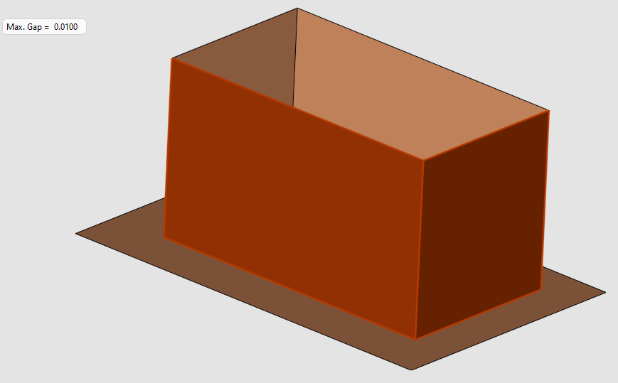
Enter a value for the Max. Gap parameter.
(The Parameters section below provides a definition of the Max. Gap parameter as well as the other parameters available for this function.) -
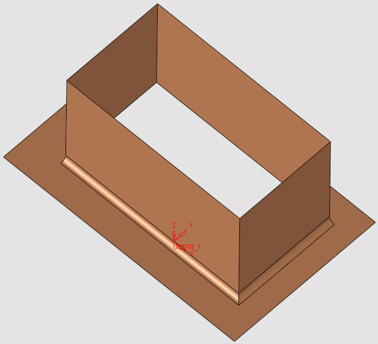
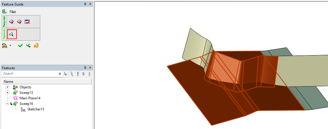
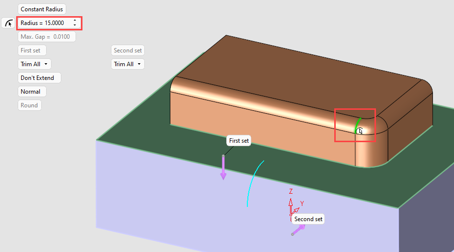
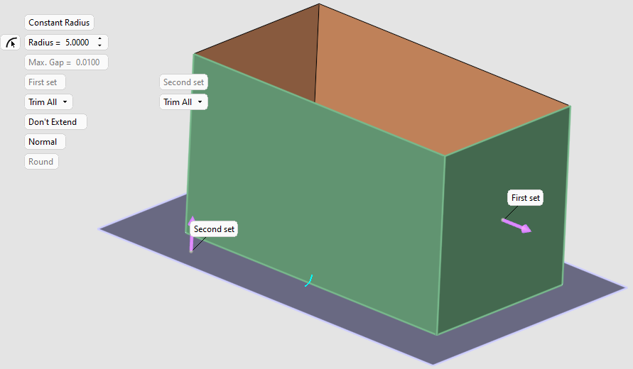
PickPick the first set of faces - Picked faces are displayed in brown.
-
When you have finished selecting the first set of faces, exitexit to proceed to Required Step 2.
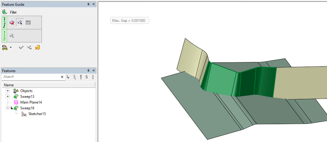
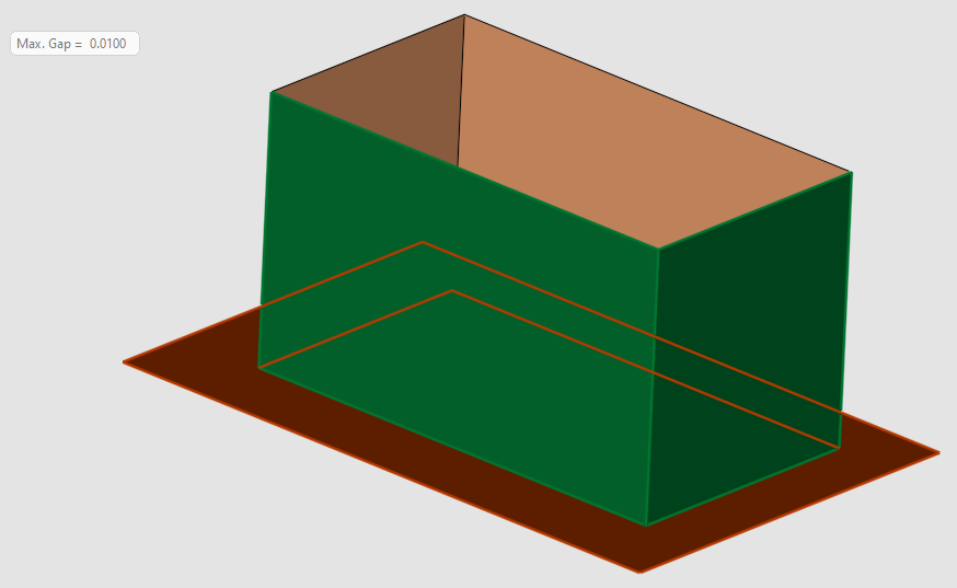
In the example above, all vertical faces have been picked (shown highlighted in green).Cimatron performs a check after a set of faces are selected. Any gaps within a group of faces that exceed the Max. Gap value are highlighted on screen, these gaps must be removed before you can proceed. The gap may be a space between edges or excessive overlap, and may only affect a portion of the highlighted edge.
Required Step 2
-
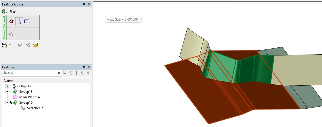
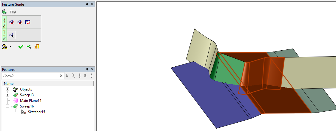
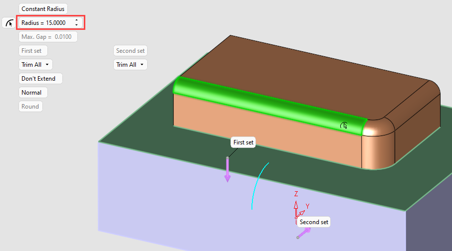
Pick the faces for the second set - Faces selected in the first step are displayed in green. Faces picked in this step are displayed in brown.
-
When you have finished selecting the second set of faces, exitexit to proceed to Required Step 3.
In the image above, faces selected in the second set are highlighted in purple.Cimatron performs a check after a set of faces are selected. Any gaps within a group of faces that exceed the Max. Gap value are highlighted on screen, these gaps must be removed before you can proceed. The gap may be a space between edges or excessive overlap, and may only affect a portion of the highlighted edge.
Required Step 3 
-
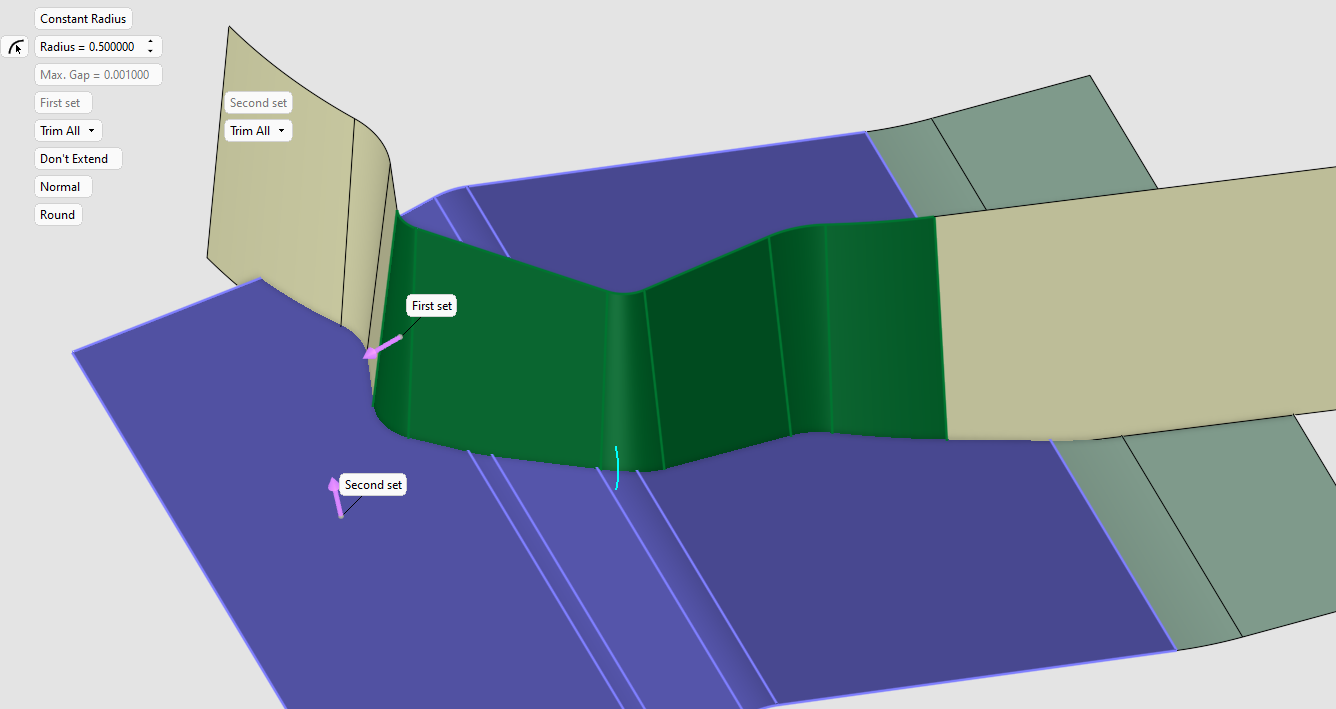
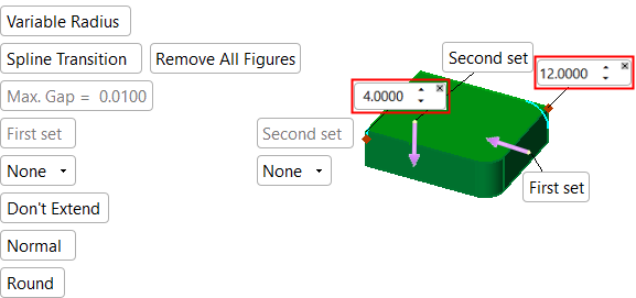
Set the parameters as required and optionally edit the direction arrows for each set.
-
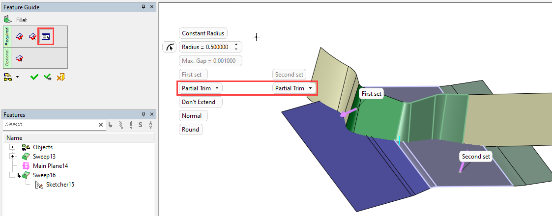
The following parameters are displayed (The Parameters section below provides a complete list of parameters available for this function with their definitions).
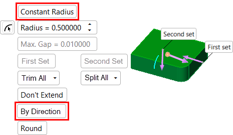
Constant Radius parameters
Variable Radius parameters
Note that the Fillet preview is displayed
(as per the Round / Flat parameter).
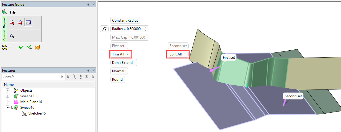
Trim Split Status indicators
The colors applied to the preview indicate which faces have been designated for trimming or splitting during the fillet operation. The darker or lighter shades of the set colors (purple and green) show which faces will be trimmed or split.
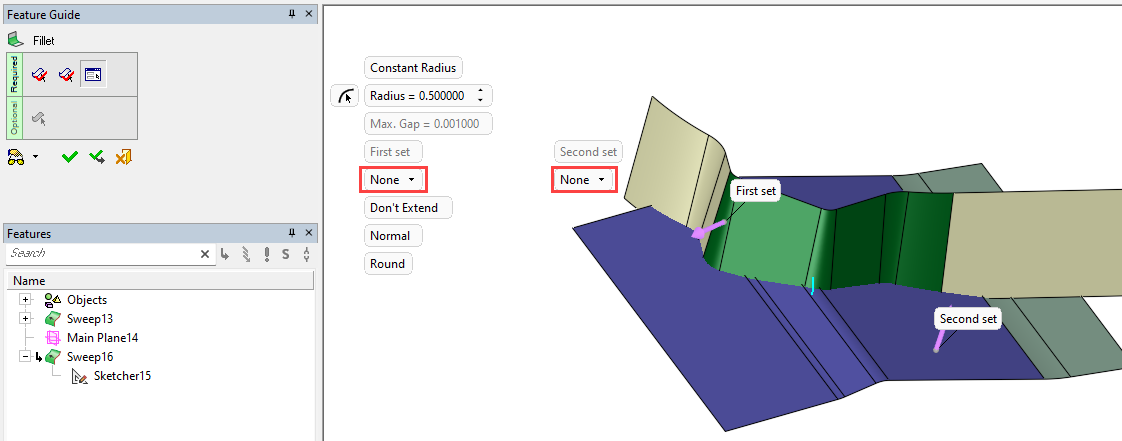
- Faces in Set 1 that are not selected for Trim or Split are displayed in the darker shade of green.
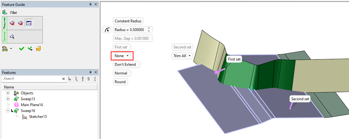
- Faces in Set 2 that are not selected for Trim or Split are displayed in the darker shade of purple.
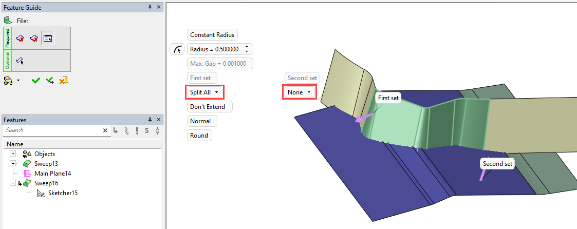
- Faces in either set that are selected for Trim or Split are shown in a lighter shade of their assigned color.
Optional Step (Constant Radius only) 
Fine tune your selection by picking any individual faces to include or exclude for Split or Trim. When you enter this step, the display colors highlight the Trim or Split status of the individual faces in each set.
- Pick which of the selected faces you wish to remove or reselect for Split or Trim. As you pick the faces, the display color will toggle from red to the original color when deselected and from the original color (fillet faces that were not selected for split or trim) back to red when they are selected, to show the status of the face.
- Single pick and box selection options are available.
- In this image, a subset of the faces have been selected.
- When you have finished, exit Optional Step 1 to return to Required Step 3.
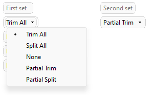
- If you selected any faces for Trim or Split in Optional Step 1, the parameter menu will identify which set has been edited by displaying Partial Trim or Partial Split. This is a status notification only and cannot be used for selection - Selection of individual faces to be trimmed or split is only available in Optional Step 1.
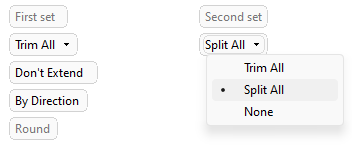
- Selections made during the Optional Step 1 (Partial Trim or Partial Split) can be reset by selecting Trim All, Split All, or None from the dropdown.
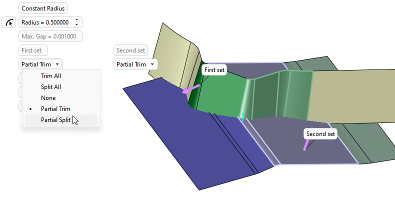
- If you selected any faces for Trim or Split in Optional Step 1, the parameter menu will identify which set has been edited by displaying Partial Trim or Partial Split. This is a status notification only and cannot be used for selection - Selection of individual faces to be trimmed or split is only available in Optional Step 1.
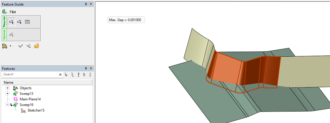
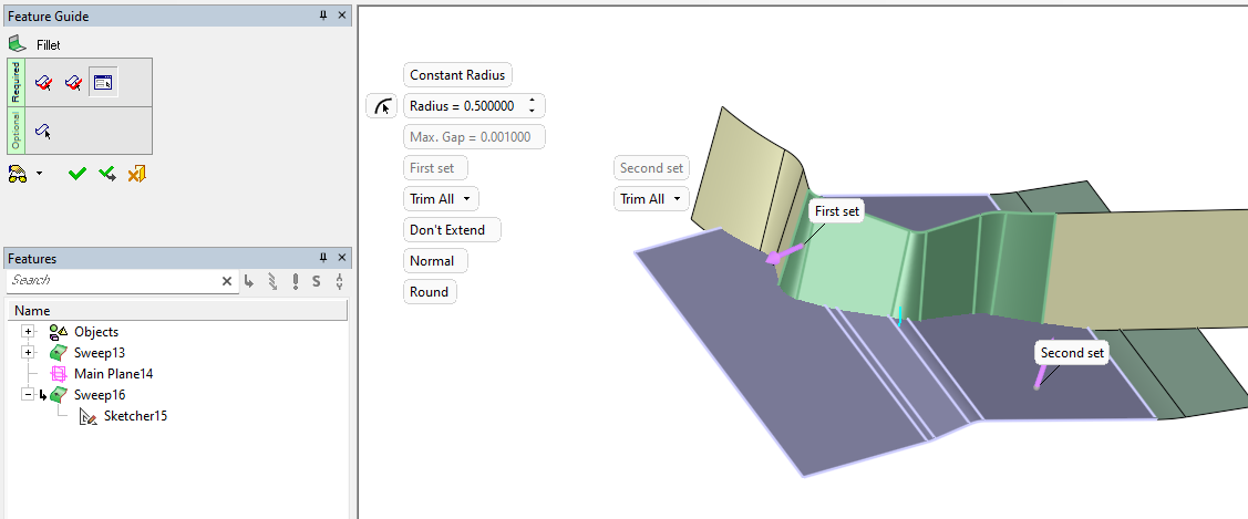
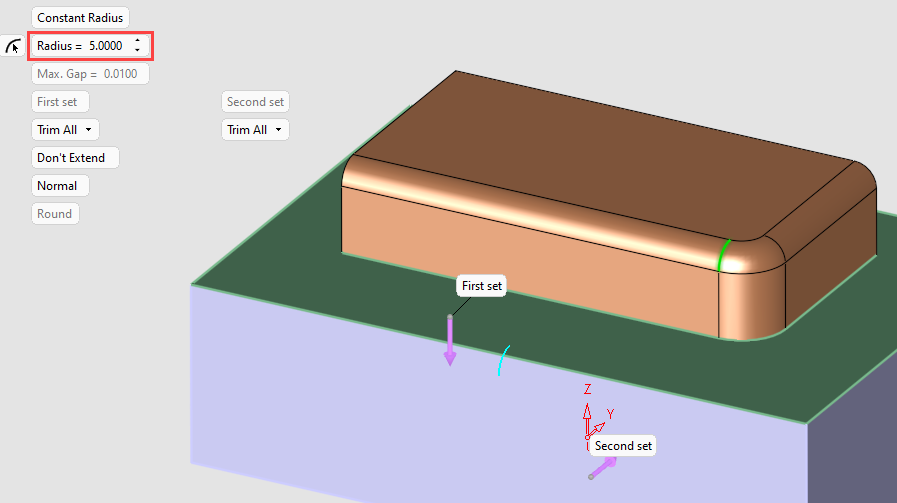
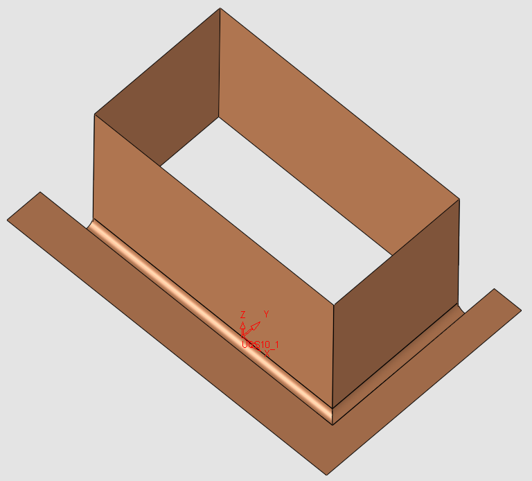
- Click OKOK
 or ApplyApply
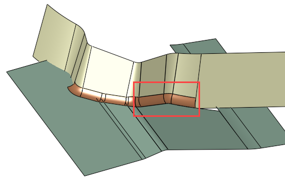
 in the Feature Guide to complete the function. A fillet is created between the face sets. The faces highlighted in the red rectangle have been trimmed, other filleted faces have not.
- When completed, the Fillet feature will appear in the Feature Tree.
Parameters
|
Constant Radius / |
This toggle option defines the type of radius for the fillet.
|
||||||||||||||||||||
|
Extend / |
When working with non-periodic groups (when the Guide Curve is not closed), this toggle parameter defines whether or not the ends of the fillet face (or group of fillet faces) will be extended to meet the boundaries of the input faces. In case of a closed Guide Curve, this parameter does not affect the result.
|
||||||||||||||||||||
|
First Set |
These parameters are not editable (are grayed out) and only function as descriptors for the two sets of faces that are defined in Required Step 1 and Required Step 2. Each set has a parameter displayed directly below it that features a dropdown list for the Trim All / Split All / None parameter that allows you to trim all faces, split all faces, or retain the original faces in a set.
|
||||||||||||||||||||
|
Normal / |
This parameter enables you to create a normal fillet or create a fillet by defining a direction.
|
||||||||||||||||||||
|
Max. Gap |
This parameter allows you to define the Max. Gap tolerance value between the neighboring faces. If the gaps between the neighboring faces are smaller than the Max Gap value, fillets are created and healed to each other. If they are larger, the fillets are not created and a warning is displayed. The initial default tolerance value is defined in Preferences, which also includes a preference setting for the tolerance range. The value for the Max. Gap parameter is defined in Required Step 1. For subsequent steps, the parameter is grayed out and cannot be edited unless you return to Required Step 1. Note: Cimatron performs a check after a set of faces are selected. Any gaps within a group of faces that exceed the Max. Gap value are highlighted on screen, these gaps must be removed before you can proceed. The gap may be a space between edges or excessive overlap, and may only affect a portion of the highlighted edge. |
||||||||||||||||||||
|
Round / |
This toggle parameter defines the resulting fillet as either Round or Flat.
When the Constant Radius option is used, a fillet preview Note that the result of the fillet face Flat option is not the same as the result produced by the Solid > Chamfer function. With the Solid > Chamfer function, the chamfer is created according to the distance from the corner edge. The Fillet face Flat option is created according to the imaginary round fillet face.
|
||||||||||||||||||||
|
Toggle parameter that is available for each set of fillet faces (selected in Required Step 1 and Required Step 2) that allows you to trim all faces in a set, split all faces in a set, or retain the original faces in a set. Individual faces can be selected or deselected in Optional Step 1.
|
|||||||||||||||||||||
Constant Radius-specific parameters |
|||||||||||||||||||||
|
Constant Radius
|
Define a fillet with a constant radius.
|
||||||||||||||||||||
|
Radius |
Enter the desired constant Radius for the fillet. The Radius can either be set by entering the required value into the field or selecting |
||||||||||||||||||||
|
|
Define the radius value by picking an arc, cylindrical face, torus face, or a point (for point, see the note below). The Radius value is set according to the radius value of the selected geometry (the value is not associative to the selected geometry. This is simply a quick way of setting the radius based on existing geometry).
Note: A point can also be used to define the radius value. To enable you to pick a point, manually select the Point option in the Selection Filter. This automatically selects the Close to Face point filter option. This enables you to pick the closest point to any face (except a planar or planar nurb) and the minimum radius at this point is selected. |
||||||||||||||||||||
Variable Radius-specific parameters |
|||||||||||||||||||||
|
Variable Radius |
Define a fillet with a variable radius.
To set variable radius values for the fillet, pick any point on the First or Second set of picked faces or on their edges. You can use any of the Point Selection options to select the points. A parameter label is attached to each picked point. Edit the parameter labels to set the radius value at each point. The point is also marked with a preview arc displaying the size and shape of the intended fillet using the current parameter values.
|
||||||||||||||||||||
|
Linear Transition / |
This toggle parameter defines the type of transition between the various radii.
|
||||||||||||||||||||
|
Remove All Figures |
Click this parameter to remove all the radius value labels from the display. |
||||||||||||||||||||

Multi-Face example of external sharp corner
Required Step 1
PickPick the first set of faces - As they are picked, faces are displayed in brown; When you exit this step they are displayed in green.
Required Step 2
Pick the faces for the second set - As they are picked, faces are displayed in brown; When you exit this step they are displayed in purple.
Required Step 3:
Set parameters as required.
Click OK ![]() or Apply
or Apply ![]() in the Feature Guide to complete the function.
in the Feature Guide to complete the function.
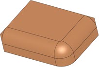
Results with Trim All
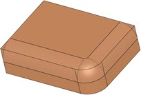
Results with None