|
|
Automatic Ordinate  : Dialog

Access: Open this function from one of the following locations:
-
Click the
button in the toolbar. -
Select Symbols > Automatic Symbols > Automatic Ordinate from the menu bar.
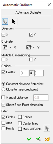
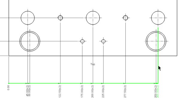
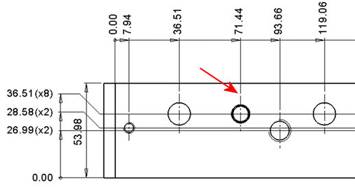
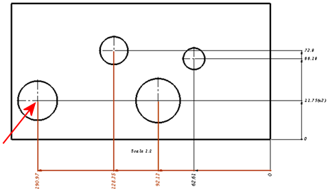
Automatically create ordinate dimensions through circles, arcs, points, splines, and center lines.
Ordinate dimensions can be created in any direction and defined via view entities (two points or a line), allowing alignment with view rotation or angled details. You can also control the ordinate dimension's association with the view on the X-axis as well as its distance from selected points or the view. Additional functionality includes the option of displaying the Base Point dimension (zero point).
Preferences options enable you to set the default for the creation of ordinate dimensions close to the measured point or outside the view and also the default distance of the ordinate dimensions.
The dialog elements for this symbol are described below.
The Automatic Ordinate dialog is displayed:
|
|
When creating ordinate dimensions on Center Lines, the dimension lines start from the end of the center line, rather than the center of the circle, to create a clearer view. Note that this only works when Center Lines are selected in the dialog (in the Filter section) and Circles are not.
|
To edit (or to re-position) a symbol after it has been created:
Double-click the appropriate symbol. The relevant dialog associated with the symbol is displayed. This means that you are now in edit mode.
Edit the symbol elements and/or re-position the symbol as required.
Symbol Elements
|
Select Base Point |
Pick the dimension base point. This button is selected by default and can be reselected to pick a different base point. |
|||||||||||||||||
|
Set Ordinate Direction |
Define the direction of the dimension line by picking two points or a line. |
|||||||||||||||||
|
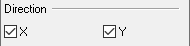
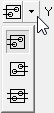
Direction |
Set the direction on the X, Y axis or both.
|
|||||||||||||||||
|
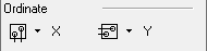
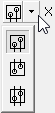
Ordinate |
Set where the ordinate dimension will appear in relation to the view.
|
|||||||||||||||||
|
Multiple Dimensioning |
Set multiple dimension ordinates for each point on the X or Y axis. |
|||||||||||||||||
|
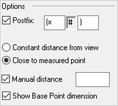
Options |
Set the required option(s) for the operation.
|
|||||||||||||||||
|
Filter |
Set the required filter option(s) to include or exclude geometric entities in the operation.
|


Dialog Buttons
|
|
Restore Default: Reset all values and settings to the system defaults. |
|
|
OK: Accept the changes, perform the operation, and close the current dialog/task. |
|
|
Apply: Accept the changes, perform the operation, and keep the current dialog/task open. |
|
|
Cancel: Cancel all changes and close the dialog/task without saving the settings. |
|