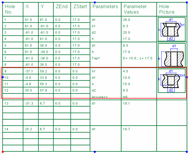
Table of Holes: Defining Sketch Holes 
Access: Open this function from one of the following locations:
-
Click the
 button in the toolbar.
 -
Select Symbols > Tables > Table of Holes from the menu bar.
Define new holes within the Table of Holes (ToH) by selecting Sketcher entities (points and circles) that were created in the view from which the TOH was generated. These Sketcher entities can be created either in the Part or Drafting environments. There is no need to create the actual holes in the model and model is not updated; the new holes exist only in the ToH.
For example, in the plate below, there are some points and circles created in the Sketcher (in addition to the holes). Use this function to add these entities, as holes, to the ToH.
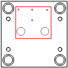
Define new holes from Sketcher entities
-
InvokeInvoke the Table of Holes dialog. From this dialog, click the Sketch Holes Selection
 button to define Sketcher entities as new holes in the Table of Holes.
The following screen option is displayed:

Automatic
This is a toggle option: Automatic / Manual.
Automatic
Pick a sketch circle that is to be defined as a hole and added to the Table of Holes. All circles with the same diameter are automatically selected. To unselect specific circles, re-pick the appropriate circles individually.
Points cannot be selected by using the Automatic toggle option.
Manual
Individually pick each sketch entity (points and/or circles) that is to be defined as a hole and added to the Table of Holes. To unselect specific sketch entities, re-pick the appropriate entities individually.
In the examples below, all the Sketch entities have been added manually (By Box).
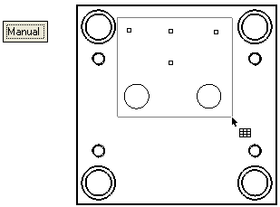
-
Click OK
 in the Table of Holes dialog. For each selected Sketch entity, a row is added in the Table of Holes.
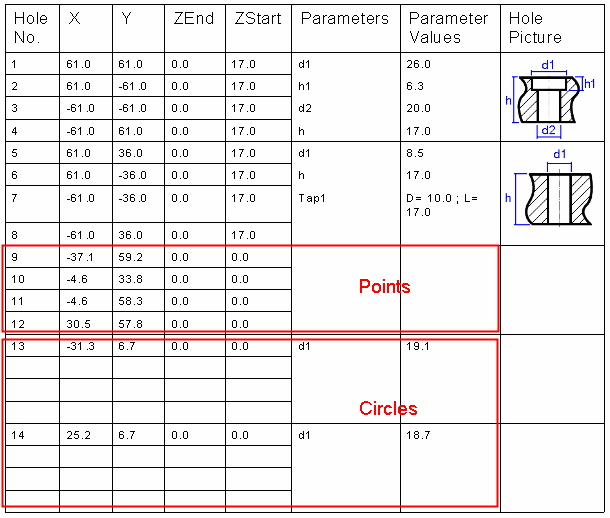
Notes:
-
The sketch entities are initially added to the Table of Holes as undefined holes (they have no Z Start values).
-
The points have their XY values added to the Table of Holes.
-
The circles have their XY and diameters values added to the Table of Holes,
-
-
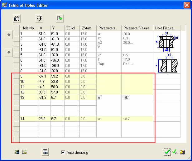
Display the Table of Holes Editor dialog. Each new row added to the Table of Holes is displayed highlighted in the Table of Holes Editor dialog as shown below:
-
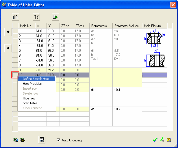
From the Table of Holes Editor dialog, right-click the grey square to the left of one of the added rows. A popup menu is displayed:
-
Select the Define Sketch Hole option.
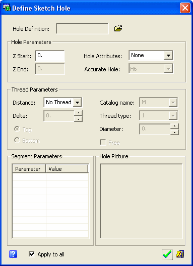
The Define Sketch Hole dialog is displayed as follows (see the parameter descriptions, below):
-
Set the Define Sketch Hole dialog parameters as required.
Hole Definition
Define the type of hole that the sketch point/circle is to represent. Press the browse button next to the Hole Definition parameter field and select the required hole type. The Cimatron Explorer is displayed and shows the available hole types in the folder:
...\ProgramData\Cimatron\Cimatron\2024\Data\HolesAs you select a hole type, a preview image of the hole is displayed in the right-hand pane of the Cimatron Explorer.
The selected hole type is displayed in the Hole Definition parameter field; the relevant Segment Parameters are displayed, as is the appropriate picture of the hole type.
ExampleExample: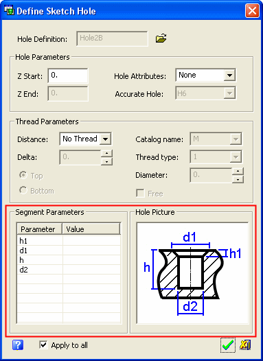
Hole Parameters
Set the relevant Hole Parameters values; the Z Start and also the Hole Attributes and Accurate Hole values as appropriate.
ExampleExample:
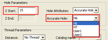
Note: Only the Z Start value can be edited. The Z End value is automatically updated according to the Z Start value and the H value of the hole (as defined in the Segment Parameters section of the dialog).
Thread Parameters
If the hole is to be threaded, define the appropriate thread parameters. These thread attributes are attached to the hole. The image of the hole in the Hole Picture section (see below) is updated according to the parameter values in this section.
Thread ParametersThread Parameters:Distance
Set the thread distance (length) of the hole. The following options are available from the dropdown list:
No Thread
The hole is not threaded and all the other parameters in this section are grayed out and cannot be accessed.
Full Depth
The thread extends the full depth of the hole. Other parameters in this section become available for definition.
By Distance
The thread extends by a defined distance in the hole. Other parameters in this section become available for definition.
When this option is selected, the following parameters need to be defined: Delta and either Top or Bottom. The Delta defines the distance (length) of the threaded part, from either the top or the bottom of the hole.
Catalog Name
If the hole is to be associative to a catalog catalog, define the catalog name from the dropdown list of available catalog hole names.
If the hole is not to be associative to a catalog, select the Free checkbox - see below.Thread Type
Set the thread type of the hole from the dropdown list. The list of available thread types changes according to the selected catalog name.
Diameter
Set the thread diameter. This option is only available if the Free checkbox is selected - see below.
Free
Select this checkbox if the hole is not to be associative to a catalog. In this case, the Diameter parameter become available for you to set the thread diameter.
Segment Parameters
Define values for each of the segment parameters. Double-click the relevant value field to the define values, and choose whether to apply these parameter settings to all the sketch points.
ExampleExample:Double-click the field:
Enter the value:
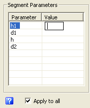
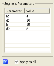
The Apply to all option enables you to apply the same parameter settings defined for one sketch point, to all the other sketch points in the same group. This also applies to sketch circles, and saves time defining the same parameters for each of the sketch entities.
Hole Picture
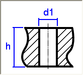
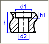
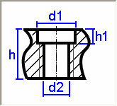
This section displays the hole you selected in the Hole Definition parameter above. The image is updated by changes in the Thread Parameters section of the dialog.
ExampleExample:Hole image without threads:
Hole image with threads (full depth):
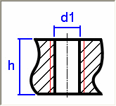
Hole image with threads (top):
Hole image with threads (bottom):
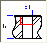
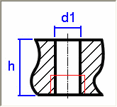
Hole image without threads:
Hole image with threads:
-
Click OK
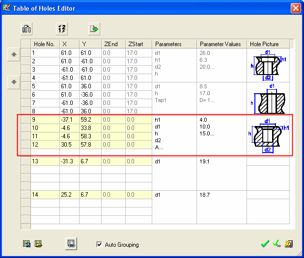
 in the Define Sketch Hole dialog to accept the changes and close the dialog. The Table of Holes Editor is then updated and displays all the changes (a message is also displayed informing you that the sketch hole is grouped).
-
Click OK
 to display the changes in the Table of Holes.
