Hatch 

Access: Open this function from one of the following locations:
-
Click the
button in the toolbar. -
Select Views > View Creation > Hatch from the menu bar.
-
Select Drafting Symbols > Hatch on the popup menu (right-click the graphics area).
Add a hatched surface to the drawing.
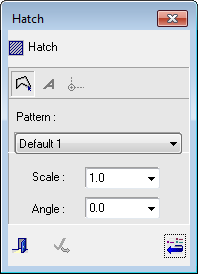
The Hatch dialog is displayed together with the following parameters:
|
|
|
Text hatch files used to define the hatch patterns have an LHC extension and are stored in the following folder:
...\ProgramData\Cimatron\Cimatron\2025.0\Data\Hatch Patterns\
Notes:
-
The default hatch pattern is defined in the Preferences > Drafting > View > Section View.
-
The default hatch color is defined in the Preferences > Drafting > General > Colors > Symbols Colors.
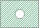
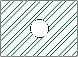
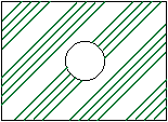
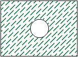
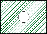
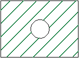
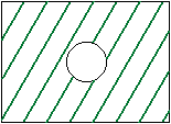
Examples
Hatch Dialog
The following buttons appear in the Hatch dialog:
|
|
Geometry button: Define the area to be hatched by picking geometry (curves, edges, etc.). |
|||||||||||||||
|
|
Text Island button: Create an island around a text box or dimension placed on a hatched surface. See Creating Islands. |
|||||||||||||||
|
|
Hatch Align button: Click the Align button and then click the point to which to align the hatch.
|
|||||||||||||||
|
Pattern |
Select the default hatch type from the dropdown menu. The newly defined hatch type is immediately applied to the selected surface.
|
|||||||||||||||
|
Scale |
Number of hatch lines: Select the scale of hatch lines from the number of lines dropdown menu or manually enter a value. The newly defined number of lines is immediately applied to the selected surface.
|
|||||||||||||||
|
Angle |
Angle of the hatch lines: Select the number of hatch lines from the line dropdown menu or manually enter a value. (The default value is 0 deg.). The newly defined line angle is immediately applied to the selected surface.
|
|||||||||||||||
|
|
Close: Close the dialog. |
|||||||||||||||
|
|
Apply: Apply the changes and remain in the dialog. |
|||||||||||||||
|
|
Reset Default button: Reset all the defaults values in the Hatch dialog. |


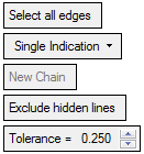
Hatch Parameters
The following parameters are displayed with the Hatch dialog:
|
Select all edges |
This is a toggle option Select all edges / Select sectioned edges.
|
||||||||
|
Single Indication |
The following dropdown options are available for defining the area to be hatched:
|
||||||||
|
New Chain |
Define a new chain. |
||||||||
|
Exclude hidden lines |
This is a toggle option Exclude hidden lines / Include hidden lines.
|
||||||||
| Tolerance | Specify the required tolerance for the hatch. |
Note: If the shade mode for M-View sectioned faces is set to Transparent, the hatch is not displayed.