|
|
Switch to CAD/CAM Mode  /
/ : Geometry Change

Access: Open this function from one of the following locations:
CAD Mode:
-
Select the Switch to CAD Mode
icon in the toolbar,
to enter the CAD
(part) environment.
-
Select File > Environment > Switch to CAD Mode from the menu bar. You are now in the part environment.
CAM Mode:
While numerous CAD options are available in NC Mode (displayed under the Curves, Faces, Tools and Analyze menus), while working in NC you may require additional CAD functionality for specific operations. To display additional CAD options, enter the CAD (Part modeling) environment by Switching to CAD ModeSwitching to CAD Mode.
(for instructions on how to invoke this function, press the Access button at the top of this Help topic)
The advantage of working in the Part environment is that you can work more completely. By using the Feature Tree, you can modify previously created geometry, delete entities, and create new geometry. Any changes you make will be maintained upon the return to NC.
Important: Changes you make in the Part environment will only affect the NC file, not the Part file! If you want to make a permanent change, work in the Part file, then update the NC file to load the modified part. See Update Mode.
Toolpath Recalculation
In many instances, changing the part’s geometry will require the recalculation of the toolpath. Accordingly, whenever there is a change to the geometry, Cimatron automatically marks relevant procedures with a geometry modification notice ("G" symbol) in the NC Process Manager, indicating that toolpath recalculation is required.
However, in other instances, changes in the part's geometry has no affect on the part to be milled (or no affect within the bounding box of the area to be milled). In these cases, Cimatron does not mark relevant procedures with the "G" symbol; see the example below.
|
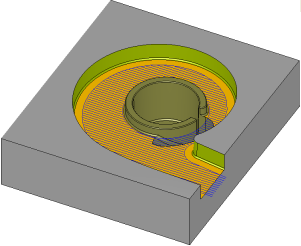
A toolpath based on the given geometry: |
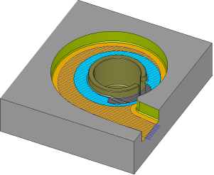
The bottom face was split into two faces (orange and cyan). However, this split operation does not really change the geometry of the part to be milled. Therefore, the procedure creating this toolpath will not result in a "G" symbol: |
This functionality can also reduce machine down time; when receiving a change and production is already underway, the machines will not have to remain idle for long while the programmer checks whether or not toolpath recalculation is necessary. |
|
|
|
|