Interactive UCS
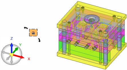
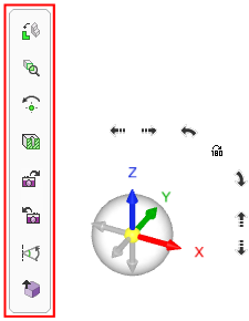
The Interactive UCS and associated toolbar are, by default, displayed at the bottom-left corner of the Cimatron graphics window (when a file is open). They are used for easy control over rotation, orientation, and the direction arrow.
|
|
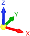
Axis colors: RED = X axis GREEN = Y axis BLUE = Z axis |
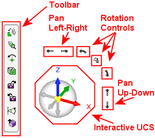
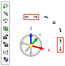
When hovering close to or over the Interactive UCS, additional operations are displayed:
|
|
Any item that the cursor is on is highlighted. The location and size of the UCS and the display characteristics (opaque or transparent) of the toolbar and the negative axes of the Interactive UCS can be defined in the Preferences. See: Note: The controls shown in the image on the left cannot all be displayed at the same time; they are all shown here together for illustrative purposes. |
Notes:
-
For additional display manipulation options, see Zoom, Pan, and Rotate (ZPR).
-
Also, see the various view display options.
UCS
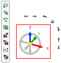
The Interactive UCS (and the negative axes) are highlighted in the example below. They are used for easy control over rotation, orientation, and the direction arrow.
Any item that the cursor is on is highlighted. The size of the UCS and the display characteristics (opaque or transparent) of the negative axes can be defined in the Preferences.
The UCS has two distinct areas:
Axes Area
|
|
The positive axes (X,Y,Z) are always opaque. When the negative axes are opaque, they are displayed grayed out. Clicking any of the axes (positive or negative axes) or clicking next to it or on the text of an axis will rotate to the plane normal to its direction. The view orientation changes, the current zoom level remains the same, and the same area of the model remains in the middle of the frame (unless you have defined a center of rotation). Dragging anywhere in the Interactive UCS area will rotate the view. The rotation is around the same point that is used for view rotation, and the current zoom level remains the same. Right-clicking the axes (positive or negative axes) or next to it or on the text of an axis will rotate to the same view, while zooming to display the entire model (Zoom All). Clicking the YELLOW ball at the UCS origin will zoom to display the entire model (Zoom All) while keeping the current view orientation. Note that if a positive axis is pointing towards you, the YELLOW ball at the UCS origin is partially covered by the axis arrow; however, clicking anywhere in the YELLOW ball area (even on the axis) will still perform the Zoom All operation.
|
||||||||
Bubble Area
|
|
Dragging one of the axes will rotate the view along the axis. The rotation is around the same point that is used for view rotation and the current zoom level remains the same. In the transparent bubble area around the positive and negative axes:
|
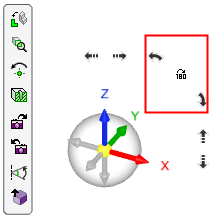
Rotation Controls
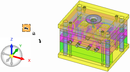
The rotation controls are on the top-right corner of the Interactive UCS, as highlighted in the example below.
The arrows enable you to rotate the view Left or Right along the axis that is perpendicular to the screen. The 180 button flips the view by rotating it 180 degrees around the Y axis of the display (horizontal flip).
Any item that the cursor is on is highlighted. The display characteristics (opaque or transparent) of the arrows can be defined in the Preferences.
|
|
Each click on an arrow rotates the view by 90 degrees. The center of rotation is always the center of the display and the current zoom level remains the same. See the examples below. |
Examples:
|
Rotate Left: Rotate the view 90 degrees to the left. |
Result: Rotated 90 degrees to the left. |
|
|
|
|
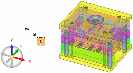
Rotate Right: Rotate the view 90 degrees to the right. |
Result: Rotated 90 degrees to the right. |
|
|
|
|
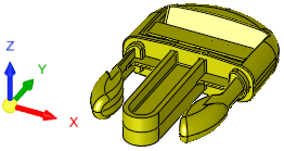
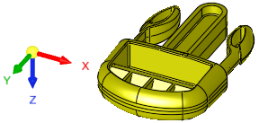
Flip View: Flip the view 180 degrees. |
Result: Rotated 180 degrees around the Y axis of the display (horizontal flip). |
|
|
|
Pan Controls
|
|
The pan controls are on the top and right of the Interactive UCS, as highlighted in the example on the left. The arrows enable you to pan the view Left or Right or Up or Down, along the axis that is perpendicular to the screen. Any item that the cursor is on is highlighted. The display characteristics (opaque or transparent) of the arrows can be defined in the Preferences.
|
Toolbar
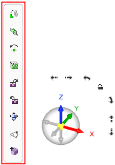
The toolbar is highlighted in the example below.
Any item that the cursor is on is highlighted. The display characteristics (opaque or transparent) of the toolbar can be defined in the Preferences.
|
|
|
|
With ZPR Lock |
Without ZPR Lock |
|
|
Rotate to a picked plane or planar face. |
|||||
|
|
Zoom to display selected entities. |
|||||
|
|
Rotate parts around a manually selected point. |
|||||
|
|
Dynamic Section creates a temporary section along a plane, which can be adjusted by moving a control in the Dynamic Section dialog. |
|||||
|
|
Display the next view orientation. This button is only available if you are not at the end of your view "list" (only available if you went back a view using Previous View). |
|||||
|
|
Display the previous view orientation. This button is only available if you are not at the beginning of your view "list" (only available if you change the view orientation or went forward a view using Next View). |
|||||
|
|
Zoom, Pan, and Rotate as if the CTRL key is pressed down. This enables ZPR operations using only the mouse. The display of this option is controlled in the Preferences. If the Show ZPR Lock button on interactive UCS toolbar checkbox is ON |
|||||
|
|
Rotate each axis by a defined angle. |
|||||
|
|
+Z / -Z ISO View |
This is a toggle button with two modes, as follows:
|

Notes:
-
For additional display manipulation options, see Zoom, Pan, and Rotate (ZPR).
-
Also, see the various view display options.