|
|
Analysis (stock) Docking Pane
Stock analysis applies coloring schemes to the material in process (stock) that allow the user to analyze areas of the stock after cutting or adding material, or, for some analyses, even the entire stock.
A separate docking pane is created for each stock present in the simulation (for example, for mill-turning machines with two spindles, where a stock appears on the left spindle as well as on the right one). The name of the stock to which the analysis refers will appear in parentheses in the title of the docking pane.
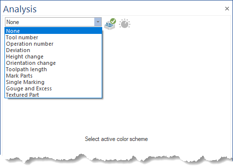
None
No color scheme is applied to the stock, so the color for areas where material has been removed or added is the same as the rest of the unmodified stock parts, and is the color set in the machine definition for the respective stock geometry.
Tool Number
The remaining material after tool cutting will be colorized based on the tool number provided in the CAD/CAM system.
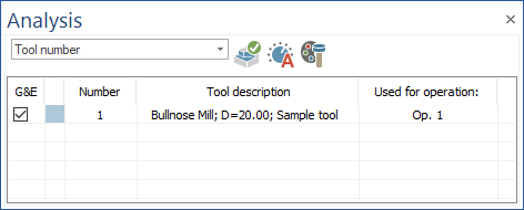
Used to identify the amount of different tools being used and the areas where a certain tool is performing a machining.
-
Number: The tool number given in the CAD/CAM system.
-
Tool description: Information regarding the tool type, tool diameter and the comment from the simulation file, describing the tool
-
Used for operation: The operation where the respective tool has been used during the simulation run.
-
G&E check-box: Show or hide labels containing information about gouges and excesses for material that is cut by a tool (in other words, do not show or hide the labels reported for material not cut/untouched by a tool).
-
Color change: Double-click on each color to display the dialog for choosing the colorization scheme for each tool.
-
Refresh: Applies the changes done in the Color Change area to the stock colorization scheme.
-
Auto-Adjust: Resets the colorization scheme to the default colors.
-
Match tool flute color with cutting color: By activating the Match Tool Flute Color with Cutting Color button, the tool flute will take the same color as the area machined with the respective tool.
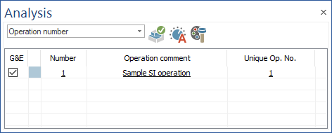
Operation Number
The remaining material after tool cutting will be colorized based on the operation.
-
Number: represents the tool number given in the CAD/CAM system.
-
Operation comment: represents the operation comment from the simulation file.
-
Unique Op. No.: represents the order of each operation in the simulation
-
Match tool flute color with cutting color: By activating the Match Tool Flute Color with Cutting Color button, the tool flute will take the same color as the area machined with the respective tool.
-
G&E check-box: show or hide labels containing information about gouges and excesses for material that is cut by a tool (in other words, do not show or hide the labels reported for material not cut/untouched by a tool).
-
Color change: by double clicking on each color, a dialog for choosing the colorization scheme for each operation is opened.
-
Refresh: Applies the changes done in the Color Change area to the stock colorization scheme.
-
Auto-Adjust: Resets the colorization scheme to the default colors.
Deviation
The Deviation functionality will display the differences between the process stock and the target (workpiece) geometry.
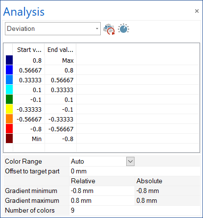
The colors that appear on the in-process stock represent regions with more or less material compared to the target geometry (workpiece). This identifies the amount of material remaining on the target geometry, identifies gouges, when too much material has been removed and the target geometry is no longer respected, identifies the area where rest machining is required, and identifies, with appropriate fine settings, small imperfections in the cutting process.
-
Start value & End value: The interval of deviation for which the respective color will appear.
-
Color Range
-
Auto: In this mode, the Start value and End value for each interval (color) will be determined automatically, except for the middle interval (green), which is based on the Collision Tolerance value. When switching to it from "Manual" mode, the number of colors will be set to an odd number by removing one color if there is an even number of colors, and, at the same time, the colors will be redistributed in the form of a gradient.
-
Manual: Allows user to change the color and "Start value" and "End value" of each interval (incl. middle (green))
-
-
Offset to target part: it establishes an offset for the target part (presumes the target part (workpiece) is smaller or bigger with the indicated value). This will be reflected only in the fields "Absolute", while all the other values will remain relative to the given offset value.
-
Gradient minimum
-
Relative: it allows user to establish a new minimum for the graident of color. In case "Color range: Auto", the other intervals will be automatically recalculated (except the middle, green color). In case "Color range: Manual" it will change only the last End value and penultimate Start value. The value introduced should be bigger than penultimate End value.
-
Absolute: it displays the absolute value for the minimum gradient based on the "Offset to target part" value.
-
-
Gradient maximum
-
Relative: it allows user to establish a new maximum for the graident of color. In case "Color range: Auto", the other intervals will be automatically recalculated (except the middle, green color). In case "Color range: Manual" it will change only the first Start value and second End value. The value introduced should be bigger than penultimate Start value.
-
Absolute: it displays the absolute value for the maximum gardient based on the "Offset to target part" value.
-
-
Number of colors: works only in case "Color range: Auto" and allows user to change the number of colors used to analize the deviation. Each interval Start value and End value are automatically recalculated (except the middle, green color). The number of colors is always an odd number.
-
Refresh: Applies all the changes made to the stock colorization scheme. This may include also a recalculation of deviation.
-
Min/Max Detection: Automatically detects the Gradient minimum and Gradient maximum values by calculating gouges and excesses for entire part. This may take some time in some cases (depends on the part complexity and how much material is removed). In case of Color range: Auto, all intervals will be automatically recalculated (except the middle, green color). In case "Color range: Manual" it will change only the last End value and penultimate Start value and the first Start value and second End value. The canges will appear only if the detected Gradient minimum value is bigger than penultimate End value, and the detected Gradient maximum value is bigger than penultimate Start value.
Note: In both cases, for the last color to be used when this function is used, the "Gradient minimum" and "Gradient maximum" values will be calculated by subtracting the Collision Tolerance value from the actual internally calculated gradient values.
-
Color change: by double clicking on each color, a dialog for choosing the colorization scheme for each interval is opened. This works only for "Color range: Manual"
-
Context menu: appers when user use right-mouse-click on the color and interval area.
-
Insert color above: works only for "Color range: Manual" and inserts a color above of the selected interval. The color will be automatically choosen as a gradient between the colors of the intervals where this will be inserted. The Start value and End value for new interval will be automatically calculated, by recalculating all values from the middle color (green) till the end (Min or Max - depends on where the color was added).
-
Insert color below: works only for "Color range: Manual" and inserts a color below of the selected interval. The color will be automatically choosen as a gradient between the colors of the intervals where this will be inserted. The Start value and End value for new interval will be automatically calculated, by recalculating all values from the middle color (green) till the end (Min or Max - depends on where the color was added).
-
Remove selected colors: works only for "Color range: Manual" and removes the select interval. The Start value of the above interval will be copied as End value of the below interval, to allow proper connection.
-
Reset Settings: appears always (even if "Color range: Auto" or "Manual") and reset all settings to defaults. Gradient minimum and Gradient maximum values are calculated based on the Collision Tolernace value, "Color range" is set to "Auto", and "Number of colors" is set to default. The intervals values are evently split.
-
Height Change
The height change indicate whether the tool is diving or being pull into and from that material.
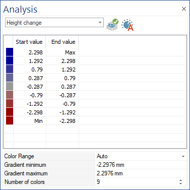
Used to identify the cutting method (Zig Zag or OneWay) and identify if there are plunge motions in the material. In this case the tool must be able to perform plunging.
Orientation Change
The material will be colorized after the orientation change of the machines rotation axis.
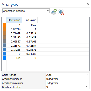
Identifies the rotation speed range being used and under which rotation speed a certain area is machined - The rotation speed gives feedback where machine speed limits are reached and where you can expect stability issues of the process which influences the final surface quality.
Toolpath Length
The toolpath length indicates the length of the toolpath segments.
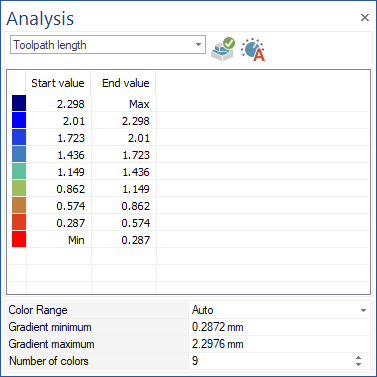
Used to identify if the toolpath points are equally distributed on the work piece. A constant distribution generally is better for the machining process and stability.
Mark Parts
The part will be colorized into chips which have been separated from the main part.
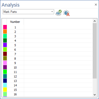
Used to identify the chips which result after the machining.
Single Marking
This option will color the cut material in the part.
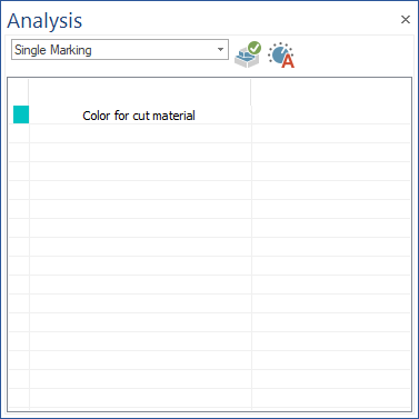
Used to identify the areas of the part where the material has been removed.
-
Refresh: Applies the changes done in the Color Change area to the stock colorization scheme.
-
Auto-Adjust: Resets the colorization scheme to the default colors.
Gouge and Excess
The option will display the areas of the stock where there are gouges, excess material, or the material is in threshold, compared to the target part.
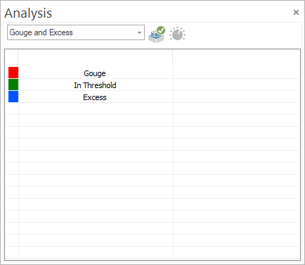
Used to identify the areas with excess material left on the target geometry, areas where a rest machining is necessary, areas where gouges occur, when too much material was removed and the target geometry is being damaged, and identify the areas that are within the defined precision.
-
Refresh: Applies the changes done in the Color Change area to the stock colorization scheme.
-
Auto-Adjust: Resets the colorization scheme to the default colors.
Textured Part
The option will apply textures on the part, for both the cut and uncut material. By default, the set texture is a wooden one.
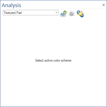
For the option to be shown in the list, the texture files for cut and uncut material should be in the sample folder (for the wooden texture, the Wood_cut.bmp and Wood_uncut.bmp files should both be present in the sample folder). Used to simulate the material used to make the part.
-
Show Collisions plus Textures: display also the collision coloring for the textured part.
|