|
|
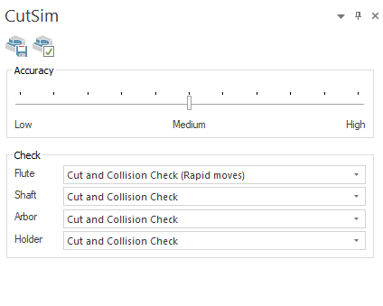
CutSim Docking Pane
The CutSim docking pane is where you configure settings for Material Simulation.
The Machine Simulator employs a state-of-the-art engine and data model for all material removal and additive simulations.
Accuracy
-
Accuracy: This defines the resolution of the stock model. Low accuracy increases simulation speed but yields less precise results. Conversely, high accuracy decreases simulation speed, but enhances the model's resolution.
-
Check: Determine whether a tool part should remove material, be checked for collisions with in-process stock material, do both, or remain inactive.
-
Flute
-
Cut: The tool part performs material removal without collision checking.
-
Cut and collision check (rapid moves): The tool part performs material removal and collision checking, but only for the RAPID moves.
-
-
Shaft, Arbor and Holder
-
None: The tool part performs neither material removal nor collision checking.
-
Cut: The tool part performs material removal without collision checking.
-
Cut and Collision Check: The tool part performs material removal and collision checking.
-
-
Save Stock 
The stock model shown in the graphical area can be saved to an STL file.
-
Custom Resolution: Specifies the quality of the saved mesh and determines the size of the output STL file, for more see Custom Resolution.
When there is more than one stock in the simulation, this option will output:
-
one STL file with the specified name that contains all meshes, followed by
-
additional STL files for each stock in the simulation, with file names consisting of the specified name followed by "_stock" and an index number.
Advanced Properties 
The advanced properties button opens the Parameters dialog.
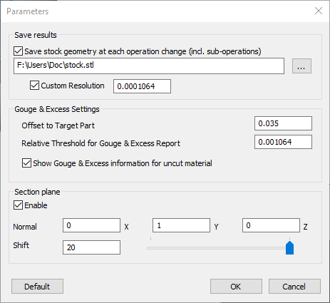
The dialog lets you adjust the following settings:
-
Save results: Save the stock geometry after each operation change. Sub-operations are treated as distinct operations and, therefore, constitute an operation change.
-
Save stock geometry at each operation change (incl. sub-operations): Create stock STL files that are saved in the user-specified folder. With each operation change, a new file is generated with the given name followed by a sequentially indexed number.
-
Custom Resolution: Specifies the quality of the saved mesh and determines the size of the output STL file, for more see Custom Resolution.
-
-
Gouge & Excess Settings
-
Offset to Target Part: Set the offset value used during the Gouge & Excess calculations.
-
Relative Threshold for Gouge & Excess Report: Set a threshold for the Gouge & Excess calculations.
-
Show Gouge & Excess information for uncut material: Show/hide Gouge & Excess information for the uncut material.
-
-
Section plane
-
Enable: Enable/disable section plane functionality.
-
Normal (X, Y, Z): Define the plane that will be used as the section plane.
-
Shift: Define a shift value, that will be used to move the section plane.
-
|