|
|
Measure Docking Pane
Measure provides different features to measure out the stock (in process material) or other elements, to remove chips and refine the stock.
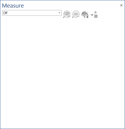
Off
This disables the usage of the mouse combination (default middle-mouse-click) that is used in most of the measure functions.
It also hides all the markings set for points, distances and the refine box, resetting the refined stock to its default state as well.
Points
The point gives information about the current coordinates x, y and z; the tool being used; block number, and the deviation.
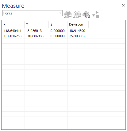
The information that will appear in the Docking Pane are:
- X, Y, Z: which represents the coordinates, relative to the workpiece, of the point(s) selected on the stock
- Deviation: which represent the deviation value in that point without offset
By right-mouse-click in the Docking Pane a Context Menu will appear. This will allow following actions:
- Remove selected items: using this option, the user can remove the items (points) that he previously selected
- Remove all items: using this option, the user can remove tall items (points)
Usage
- Move the cursor onto the stock
- Use the mouse button assigned to this action (see above)
- A point will be shown and a text box will appear in the simulation window
- The selected point will also appear in the Docking Pane point list
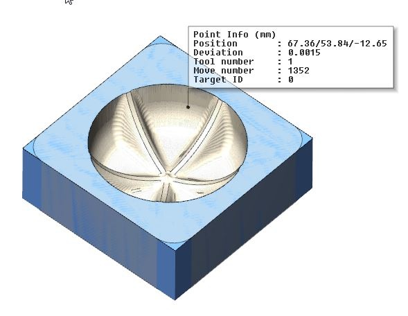
Text box
- Position: are the coordinates of the point displayed as X/Y/Z, relative to the workpiece
- Deviation: is the rest material distance to the target part (workpiece). Negative values means gouge (too much material cut in comparison with target part). Positive value means excess (not entier material is cut in comparison with target part). The value is calculated without the offset and is defined as Deviation abs. and with the offset, and is defined as Deviation rel.
- Tool number: indicates the last tool being used to cut that point.
- Move number: indicates the block number where the cut, containing the point, was done
- Target ID: indicates the stock that contains the point. For only one stock Target ID is 0
Distance
The distance measures the 3D distance between two points on the stock model.
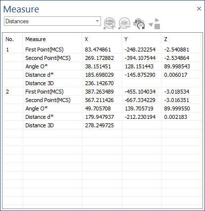
It can be also used for measuring distances between other geometries and stock, or even between two arbitrary geometries from the screen.
The information that will appear in the Docking Pane are:
- First Point (MCS) X, Y, Z: which represents the coordinates of the first point, relative to workpiece
- Second Point (MCS) X, Y, Z: which represents the coordinates of the second point, relative to workpiece
- Angle O* X, Y, Z: which represents the angle between the segment defined by the two selected points and axes X, Y and Z
- Distance d* X, Y, Z: which represents the distance between the two points, measured on axes X, Y and Z
- Distance 3D: which represents the 3D distance between the two points
Right-mouse-click in the Docking Pane to display a Context Menu allowing the following actions:
- Remove selected items: Remove the previously selected items (distances)
- Remove all items: Remove tall items (distances)
Usage
- Move the mouse cursor on the point where you want to start the measuring
- Use the mouse button assigned to this action (see above) to select first point
- Move the mouse cursor on the point where you want to end the measuring
- Use the mouse button assigned to this action (see above) to select the second and last point
- A distance value will be shown in a small text box in the simulation window. The information in the text box is the 3D distance between the two selected points.
- The selected points will also appear in the Docking Pane point list together with more informations.
Text box
- Distance: the value is the 3D distance between the two selected points.
Refine Box
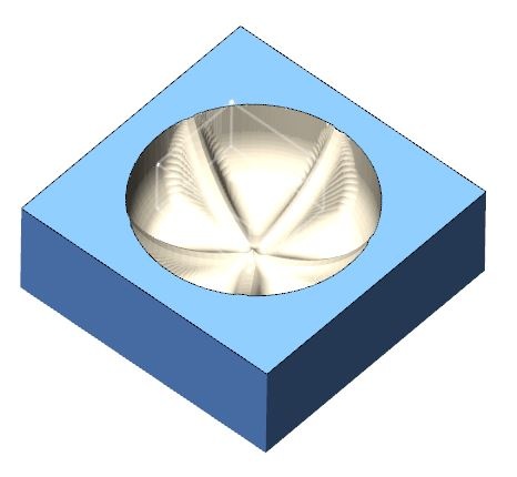
Use the zoom box to zoom into a certain area of the stock model.
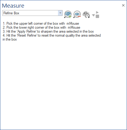
The material around the zoom box will be removed, but therefor has the new area higher resolution.
Usage
- Move the cursor onto the stock.
- Then click with the middle mouse button to select the start point and an end point of the zoom box.
- Go close to a point after the box was created and click with the middle mouse button to correct the position.
- Use the zoom-in button to activate the zoom.

Note that you can repeat the zoom onto the new area as well. - Use the zoom-out button to get to the previous zoom stage.

Note: For a faster and simpler use of this functionality, you can also try the Refine functionality from VERIFICATION - Material Removal Analysis Ribbon Bar.
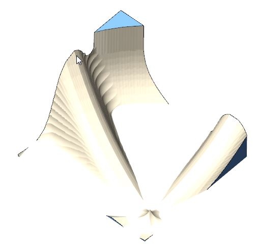
Remove chips (select chips)
Remove single selected fragments (select chips).
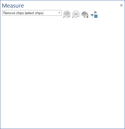
With this function the user can delete chips, which are free floating around the actual part. Simply select the chip segment and it will be removed.
Remove chips (only keep 1 part)
Only can keep the selected part of the stock (only keep one part).
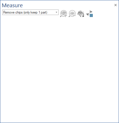
With this function the user can keep the selected part of the stock (only keep one part).
Remove chips (auto, define targets)
Keep selected fragments (select chips)
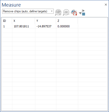
With this function the user can keep chips, which are selected. This is done simply by selecting at least one point, that belongs to the the chip(s) that user would like to keep, and the rest of them will be removed. This is done when they are encountered during simulation (if the points selection was done previously), or in anytime when Refresh button is accessed.
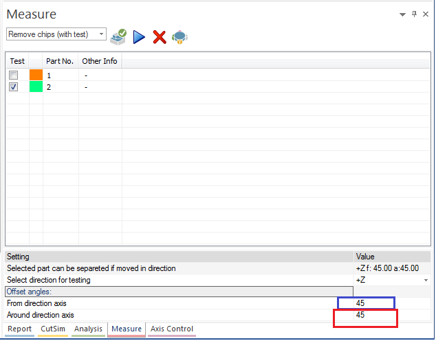
Remove chips (with test)
Remove or test selected fragments (select chips).
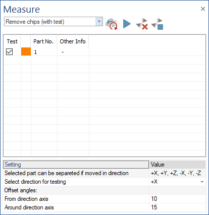
With this function the user can remove/test chips, which are selected. This is done simply by selecting the the chip(s) that user would like to keep/remove/test and then by using one of following functionalities:
- Test: this will move selected chips in the direction that is set for "Select direction for testing". The test is also taking into consideration the offset angle from the direction axis and the offset angle around the direction axis
- Remove selected parts: by using this option, all selected parts will be removed
- Stop on new chip detection: by using this option, a popup notification will show up, whenever a new chip is detected. This is common to all remove chips options.
The Remove Chips parameters From direction axis and Around direction axis simulate the chip removal process on any direction.
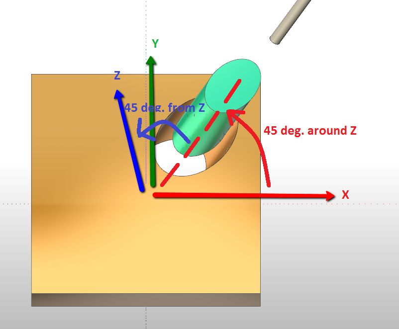
The two parameters extend the spectrum of allowed directions for chip removal to remove a chunk on an offset direction from a main axis, an offset direction around a main axis, or both. The offset values are configured by the user.
Remove chips (based on volume)
Remove chips function of the their volume.
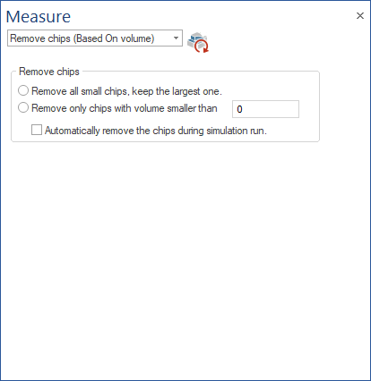
With this function the user can remove chips, based on volume, following one of following criteria:
- Remove all small chips and keep the largest one
- Remove only chips with a volume smaller than a value that can be provided by the user
The chips removing can be done automatically during simulation, by enabling "Automatically remove chips during simulation" or, if this is not checked, by using Refresh button.
|