|
|
Report Docking Pane
The Report Docking Pane collects all events which happen during simulation. The items in the report will be listed in a tree format structure.
Click on any operation or events and the simulation will jump to the position.
The Report Docking Pane has 2 sections:
-
Warning Area (upper area)
-
Report Area (lower area)
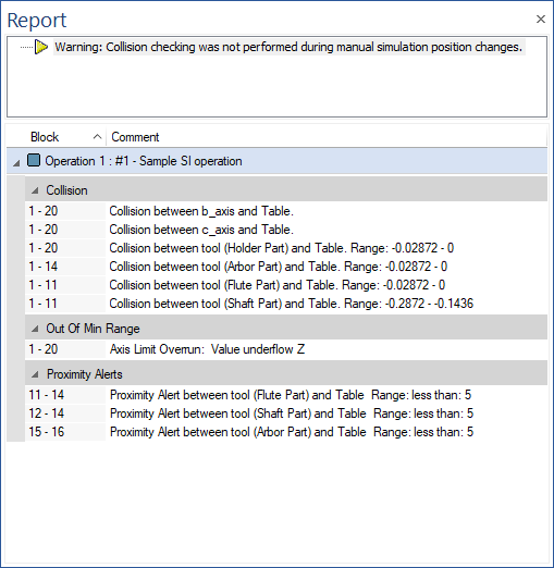
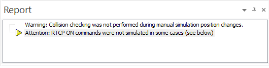
Warning Area (upper area)
General simulation messages are displayed here.
The following list shows with all the messages that could appear and their meaning:
-
Warning: Collision checking was not performed during manual stimulation position change
-
Warning: Moves outside of Refined Area will be completely ignored during simulation
-
Warning: During AQI some of the removed chips were detected as still being attached. Please review the accuracy and run the simulation again.
-
Attention: Gouge Tolerance bigger than Tool Radius (Op. #2 (5) - Tool 23). Tolerance adjusted to 0.005 for entire simulation.
-
Warning: Material Mode needed for reliable jaws clamping and collision detection
-
Attention: Continuous Collision Detection was not executed in one or more cases due to more than 180 degrees change (see below)
-
Warning: Deviation may not give perfect results due to Overlapping Triangles and/or Unmatched Edges of workpiece
-
Attention: RTCP ON command was not simulated in some cases (see below)
-
Time-based Mode was disabled due to ...% of the provided moves having their time value set to zero or missing.
Report Area (lower area)
Messages based on move and operation are shown in this area.
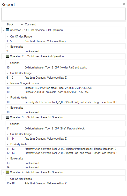
By default this area is organized with an operation followed by the tool number with the tool definition.
Below are listed all events types that can appear and all the messages:
-
Gouges&CollisionsGouges&Collisions
-
Collision between B-Axis and Table. Range: n/a
-
Collision between tool4 and Table, range: more than 1.00~
-
Collision between tool4 and Table, range: 0.50 - 1.00~
-
Gouge between tool4 Flute and workpiece. Range: 0.50 - 1.00
-
Collision between tool4 Flute and workpiece. Range: 0.50 - 1.00~
-
Collision between tool4 Flute and Table. Range: 0.50 - 1.00
-
Collision between tool4 Shaft and Table. Range: 0.10 - 0.50
-
Collision between tool4 Arbor and Table. Range: 0.50 - 1.00
-
Collision between tool4 Holder and Table. Range: more than 1.00
-
Collision between B-Axis and stock2. ~Range: n/a~
-
Collision between tool4 Flute and stock2 (on Rapid move). ~Range: n/a~
-
Collision between tool4 Shaft and stock2. ~Range: n/a~
-
Collision between tool4 Arbor and stock2. ~Range: n/a~
-
Collision between tool4 Holder and stock2. ~Range: n/a~
-
-
Material Gouge&ExcessMaterial Gouge&Excess
-
Gouge: -0.45 on stock2, pos.: 123.45/45.56/12.76
-
Excess: 0.80 on stock2, pos.: 23.54/12.56/55.88
-
-
Proximity AlertsProximity Alerts
-
Proximity Alert between tool4 Shaft and stock2. Range: less than 0.2
-
Proximity Alert between tool4 Arbor and stock2. Range: less than 0.5
-
Proximity Alert between tool4 Holder and stock2. Range: less than 2
-
Proximity Alert between B-Axis and stock2. Range: less than 5
-
Proximity Alert between B-Axis and Table. Range: less than 5
-
Proximity Alert between tool4 Shaft and Table. Range: less than 0.2
-
Proximity Alert between tool4 Arbor and Table. Range: less than 0.5
-
Proximity Alert between tool4 Holder and Table. Range: less than 2
-
- Axis Limits OverrunAxis Limits Overrun
-
Value underflow Z
-
Value overflow A
-
- Axis Values MismatchAxis Values Mismatch
-
Value mismatch T
-
Value mismatch W
-
- WarningsWarnings
-
RTCP ON "by vectors" could not be followed. Used "by machine angles" instead
-
Pick-off could not detected a valid result of Cut-off
-
Continuous Collision Detection was not executed
-
Possible collision between tailstock TS2 and workpiece
-
Possible collision between tailstock TS2 and stock
-
More than one tool is defined in the same slot tool4 (due to Multi-Stream synchronization)
-
Axis C was defined in Mill and Turning mode in the same time (due to Multi-Stream synchronization)
-
Axis A was defined with different values in the same time (due to Multi-Stream synchronization)
-
Spindle C was defined in different rotation directions in the same time (due to Multi-Stream synchronization)
-
RTCP turned OFF (unknown machine type)
-
RTCP turned OFF (undetermined tool association)
-
RTCP turned OFF (algorithm issue)
-
-
-
Bookmarked
-
- Other EventsOther Events
- Uncut Material Gouge&Excess
-
Gouge: -0.45 on stock2, pos.: 123.45/45.56/12.76
-
Excess: 0.80 on stock2, pos.: 23.54/12.56/55.88
Note: The depth of the collisions is available if the collision happens with the tool (such as range: more than 0.2).
Report - Context Menu
Right-click on the Report Docking pane to display a context menu
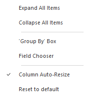
The following functionality is available:
-
Expand All Items: using this functionality, user can see expanded all the items from Report window. You can either expand or collapse the items from the report tab.
-
Collapse All Items: using this functionality, user can see collapsed all the items from Report window.
-
'Group by' Box
-
This works with "Field Chooser": this sub menu will allow user to add in Report window, all the columns that he needs (Block, Move, type, Tool, Op. Id, Comment) Used to identify to what block/move number belongs, the type of event, tool that was used, operation number, and comments for to that event
-
To group: Group the items from Report window
-
To order: Order the items from Report window
-
- Field Chooser
-
Use the field chooser to customize the layout of the report window.
-
To add a new field: Drag & Drop the block from Field Chooser to introduce any of these fields in your report tab.
-
Meaning of the fields:
-
Block - Block number in the move list for the event
-
Move - Move number
-
Type - Event type symbolized by an icon
-
Tool# - Tool number used in this event
-
Op. ID - Operation number used for the event
-
Comment - Operation comment used in this event
-
-
-
Column Auto-Resize: Automatically resize the columns from Report window.
-
Reset to default: Reset all the Report window configuration to default.
The report can be exported into a xml file by using the option from FILE - Save/Export - Create Simulation Report.
|