Graphics and Background Settings
Graphic and Background options provides settings for changing the graphic and backgrounds.
-
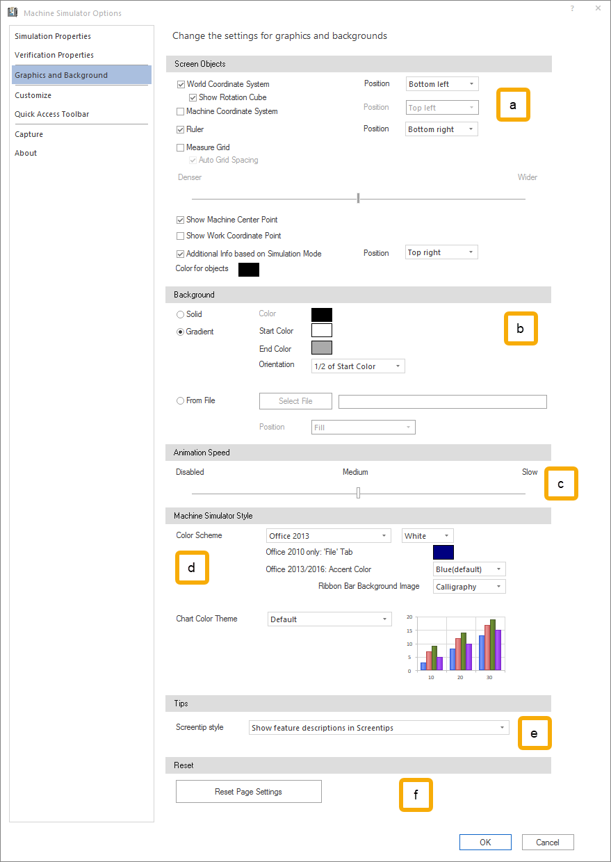
Screen Objects
This defines the position of coordinate system and the ruler in the simulation area. Further you can activate the machine center point and workpiece center point.
- Coordinate System: displays the world coordinate system for entire Machine Simulator. For more, see Simulation Area - Coordinate System and Rotation Cube.
- Show Rotation Cube: displays a cube that help rotating the elements on the simulation area. For more, see Simulation Area - Coordinate System and Rotation Cube.
- Machine Coordinate System: displays the machine coordinate system. For more, see Simulation Area - Machine Coordinate System.
- Ruler: displays the ruler that help measuring and evaluating different distances. For more, see Simulation Area - Ruler.
- Measure Grid: displays the measure grid. For more details please see VIEW - Screen Objects.
- Auto Grid Spacing: set the grid spacing automatically.
- Slider with Denser and Wider positions: when the Auto Grid Spacing is not selected, a fixed defined spacing for the grid lines can be selected.
- Show Machine Center Point: displays the machine coordinate origin point (black and white), synchronized with the machine. For more, see Simulation Area - Machine Center Point.
- Show Work Coordinate Point: displays the work coordinate origin point (blue and white), usually synchronized with the workpiece/stock and toolpath at any given time in the simulation. For more, see Simulation Area - Work Coordinate Point.
- Additional Info based on Simulation Mode: ...... For more, see Simulation Area - Work Coordinate Point.
- Position: ...
- Bottom left; Bottom Right, Bottom Center; Top left; Top rights; Top center.
- Color for objects: ...
- Position: ...
- Coordinate System: displays the world coordinate system for entire Machine Simulator. For more, see Simulation Area - Coordinate System and Rotation Cube.
-
Background
Change the background. The following options are available:
- Solid Color: a solid background color
- Gradient:
- Start Color: the color usually on the top of the simulation area.
- End Color: the color usually on the end or bottom of the simulation area.
- Orientation: can be set:
- Horizontal: the start color will be merged with the end color horizontally.
- Vertical: the start color will be merged with the end color vertically.
- Diagonal falling: the start color will be merged with the end color diagonally falling.
- Diagonal ascending: the start color will be merged with the end color diagonally ascending.
- 2/3 of Start Color: the start color will be merged with the end color horizontally and the start color will occupy 2/3 of the simulation area.
- 1/2 of Start Color: the start color will be merged with the end color horizontally and the start color will occupy 1/2 of the simulation area.
-
From File: using the Select File button the user can select a predefined picture file.
Accepted files types are BMP, JPG, PNG.
- Position:
- Center: the picture will be centered on the background of the simulation area keeping the original size.
- Fit: the picture will be resized to properly fit the simulation area in either dimensions.
- Stretch: the picture will be stretched to fill the simulation area.
- Tile: is meant for small pictures. This option will tile the same picture to fill the simulation area.
- Fill: the picture will be fitted to the simulation area while cropping away part of it.
- Position:
-
Animation Speed
Defines the speed of the animation (Disabled, Medium, Slow or in between) when using following functionalities:
- switching between different modes (Machine, Workpiece/Stock, Tool)
- switching between different views (Fit to Screen, Isometric, Top, Front, Right, etc.)
-
Machine Simulator Style
Define in which color scheme the application should appear.
The Machine Simulator User Interface can be displayed under different color schemes, with different customizable File tab (only for Color Scheme), Accent Color, and Ribbon Bar Background Image.
-
Tips
Choose how and if screentips are shown for different UI elements.
The following options are available:
- Show feature descriptions in Screentips: which will show beside the full name of the UI element also a description about what that element is supposed to do.
- Don't show feature descriptions in Screentips: which will show only the full name of the UI element.
- Don't show Screentips: will not show any screentip for any UI element.
-
Reset
Reset Page Settings: Reset all parameters to factory settings.