|
|
Ribbon Bar Simulation tab
Gives user the opportunity to directly zoom and observe elements tool, workpiece and machine in stationary position at any time. The toolbar icons contain the tools to assist user in manipulating the display and simulation.

The ribbon is divided into panes holding the controls. These panes are titled as follows:
Simulation pane
The Simulation pane groups three main settings regarding the simulation:
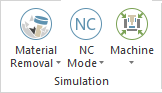
Modes
The Modes are two main ways of using the Machine Simulation.
The modes should help the user examine the two main components of the simulation: toolpath (with partial gouge & collision check) and material verification (with complete in process material (stock) gouge & collision check).
Backplot Mode

Toolpath (with target part (workpiece) visible, without material removal/additive.
Material Removal Mode

Material removal/additive full simulation.
Note:
Backplot Mode was designed to offer a good and fast overview of the toolpath and the tool movements in regard to the workpiece (ideal target part). In this mode, by default (and because there is no stock material), the workpiece and the toolpath are made visible. Also, if specified in collision checking group from machine kinematic tree, the workpiece is checked against tool cutting part for gouges and against other tool parts and machine elements against collisions.
A gouge is when the cutting part of the tool touches the workpiece with more than the tolerance provided during FEED (G1) type of moves. A collision is when the tool touches the workpiece with the cutting part during the RAPID (G0) type of moves. Also, a collision is considered when any other part of the tool or any other geometry touches the workpiece no matter the type of move.
Warning: Simulating in Backplot Mode is not intended as a simulation that will give you results to be used as "ready for real machining decision.
There are three reasons for this:
- Collision checking is done (based on defined groups) with the workpiece (an ideal target part) that in early stages of processing it looking different from what is shown on the screen. So, even if the collisions detected could be considered in most of the cases correct, in the real machining process they may happen very late.
- Gouge detection is not always accurate, due to the design approach of the detection algorithm, especially in cases where offsets are used. In some extreme cases, an offset or tolerance is not even possible, which may result in false positives or false negatives.
- Collision checking and gouge detection are not accurate in case of turning simulations when the workpiece (the ideal target part) is revolved. The accuracy of the revolved workpiece is hard-coded to offer the best between speed and quality. Some small detailed shapes that appear on the static workpiece may not appear anymore on the revolved workpiece. Still, in general, working with a revolved workpiece is much safer and better for the turning processes, that working with the static one where some gouges or collision may be missed (false negatives).
This is why we recommend always using Material Removal Mode that has all these problems fully solved.
Note:
Material Removal Mode was designed to offer results intended to be used for ready for real machining decision.
When this mode is chosen, by default, the workpiece (ideal target part) and the toolpath are hidden. Even more, we disable the workpiece collision and gouge checking from all groups defined in machine kinematic tree. The simulation runs in this mode similar to the real machine. All collisions are made with the in-process stock material. To analyze the result and decide upon ready for real machining, besides checking the Report docking pane for any messages, the Gouge & Excess or Deviation (from Analysis (stock) docking pane or VERIFICATION ribbon bar) must be also run and the results of these evaluated.
Metrics
NC-based Mode

The machining simulation only uses the NC code positions from the move list. Machine motion jumps from one position to the next.
Time-based Mode

The machining simulation will be displayed with real time feed rate motions. Machine motions are very fluent and machining time is exact.
Length-based Mode

This simulates the machining process with a constant speed, distance/time, regardless of the feed rate.
Focuses
The Focus gives the user the opportunity to directly zoom and observe elements tool, workpiece and machine in stationary position at any time.
Machine Focus

Machine and workpiece are visible. Machine is stationary, workpiece is mounted on the table.
Workpiece/Stock Focus

Only tool and workpiece visible. Workpiece is stationary, tool moves around workpiece.
Tool Focus

Only tool and workpiece visible. Tool is stationary, workpiece moves around tool.
Control
Gives control to machining process:
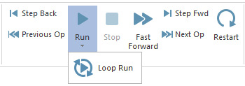
- Run: starts the simulation
- Loop Run: when this button is activated, once the simulation reach to the end (last operation, last position) it automatically starts over again.
- Fast Forward: the simulation starts from the selected step and goes to the last position of the last operation without showing the simulation process on the simulation area.
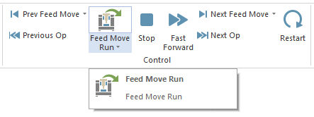
- Feed Move Run: starts the simulation simulates the rapid moves on maximum speed, and it will simulate only the feed moves with the selected speed from the speed slider.
- Stop: stops the simulation and goes to first move from first operation. Exception is when is a marker which indicates that a simulation should not start from first position of the first operation due to some preparatory moves that do not need to be simulated, but just executed in background.
- Step Back / Step Fwd: allows steps through the toolpath to the next/previous single toolpath segment. (See Note below)
- Prev Feed Move / Next Feed Move: allows steps through the toolpath to the next/previous single feed move toolpath segment, jumping over the rapid moves.
- Previous Op / Next Op: allows navigating to the next/previous operation. When the Previous Op. button is used it will jump to first move from the previous operation. When the Next Op. button is used it will jump to first move on the next operation. (See Note below)
- Restart: When this button is pressed, the machining starts over from the beginning, refreshing the stock to the initial stock, resetting all the Reports.
Note: Search Mode
During Step Back / Step Fwd and Previous Op / Next Op the Machine Simulator considers that you are in search mode. This function is design to allow you to reach quickly to the position that you want to check more in detail. To make the search faster, Machine Simulator automatically disables some collision checking and proximity alert functionalities. This is also signaled with a warning message that will appear in the Report Docking Pane (warning area) saying: Warning: Collision checking was not performed during manual stimulation position changes.
Once you reach to the desired position that you want to check it in more details, you can use either Run (Loop Run) or Fast Forward and from that point forward all will be fully checked. Still, the warning from Report Docking Pane (warning area) will not disappear until you press Restart button to make sure you are aware not everything was fully checked.
Simulation Run Speed
Controls the simulation speed during Run (or Loop Run) mode.
|
|
|
|
Slider from Ribbon Bar (or Quick Access Toolbar) which is a simplified and reduced in size |
Slider from Simulation Run Speed window which is more detailed and easy to control |
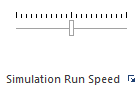
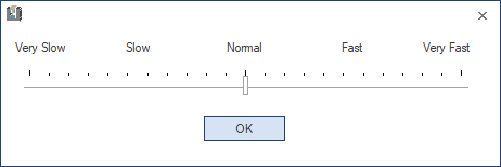
The Simulation Run Speed control bar is used to run the simulation faster/slower (or to show simulation with some steps on the display screen - usually in NC-based Mode).
There are two sliders that can be made visible:
- the slider from Ribbon Bar (or Quick Access Toolbar) which is a simplified and reduced in size version
- the slider from Simulation Run Speed window that can be activated using the small down arrow from the Ribbon Bar - Simulation Run Speed area, and which is more detailed and easy to control.
The number of steps of both sliders are identical.
The slider is divided in two parts since the speed slider is set in the middle by default. The slider has double functionality:
- 1st: the part from middle to left which controls simulation speed. ( When the slider is in the middle then simulation speed is maximum )
- 2nd: the part from middle to right which controls steps length of displaying machine simulation on the screen (Note:The simulation will run step by step but the display mode will jump from some steps).
For instance the cursor of simulation speed control bar is in the middle, it means that the maximum simulation speed is set and the simulation is shown step by step on the display screen. If the slider is dragged from middle to the left then the simulation speed will decrease and if the slider is dragged from middle to the right then the simulation speed will not change however the display mode will jump from 10 to 50 steps depending on how much the slider control is far or close to the middle of the bar. For example if the slider is dragged to the most right position of the slider, then the simulation display will jump from 50 steps. Consequently, simulation display takes place each 50 steps. If a collision is happened during these eliminated steps, then the collision will be displayed on screen.
Notes:
Expected Machine Simulator behaviours during deep analysis
The Collision Detection Setting influences the way the Machine Simulator behaves when it comes to investigating collisions in depth and when you use the simulation (Run mode) with the Speed Slider set in the Very Slow area and especially use Time-based Mode or Length-based Mode. Here are some examples of such behaviors (they are considered normal behaviors), what to expect, and how you can counteract them:
-
When Discrete Collision Detection or Continuous Collision Detection is enabled, the path followed by the machine's components may not be the one considered by either algorithm, so the following will happen:
- some collisions/gouges may be reported in the Report docking pane, but these will not be visible during the simulation run due to the different path taken;
- no collisions/gouges are reported in the Report docking pane, but different geometries can be observed on the screen intersecting each other (i.e. collisions/gouges);
- different geometries can be observed on screen intersecting each other (i.e. collisions/gouges), but no coloring (yellow/red) of the intersecting objects will occur.
All these cases of desynchronization can be avoided by enabling the Process Intermediary Positions functionality.
-
When Process Intermediary Positions is enabled, the path followed by the machine's components may not be the one considered by the algorithm due to too large values of Maximum Distance or Maximum Angle Change being used. This may cause different geometries to be seen intersecting each other on the screen (i.e. collisions/gouges), but no collisions/gouges will be reported in the Report docking pane, nor will object coloring (yellow/red) occur which intersect.
All these cases of desynchronization can be avoided by decreasing the Maximum Distance and/or Maximum Angle Change values.
Views
Manipulates the view direction of the machine and fits the elements to the screen.
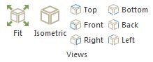
- Fit: fits all elements on the screen
- Standard view orientations:
- Isometric: rotates to isometric view
- Top: rotates to top view
- Front: rotates to front view
- Bottom: rotates to bottom view
- Left: rotates to left view
- Back: rotates to back view
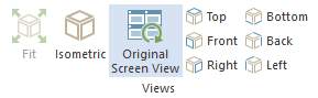
- Original Screen View: displays the initial view
Visibility
Sets certain elements to Show/Opaque/Transparent/Hide.
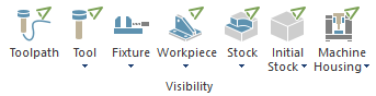
- Toolpath: the tool trajectory
- Tool: the tool itself
- Fixture: the component that grips the target part in order to fix it during machining
- Workpiece (target part): the nominal model
- Stock (in process material): the material that will be machined in order to reach the workpiece's model
- Initial Stock: the initial material that has been provided to the machine
- Machine Housing: the group of components that are not influencing the machine kinematics
Toolpath Rendering
Sets visibilities for different functions of toolpath line.
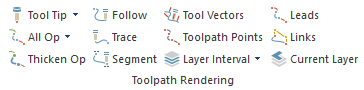
- Tool Tip / Tool Center: Displays the toolpaths on the tool tip or center
- All Op / Current Op: Shows all operations / current operation
- Thicken Op: The current simulated operation's toolpath gets thickened across its entire length
- Follow: Show only the machined toolpath
- Trace: Show only the left over toolpath
- Segment: Shows only certain amount of following and traced segments
- Tool Vectors: Shows the tool axis vectors at the toolpath points
- Toolpath Point: Indicates toolpath segment end and start with points
- Leads: Shows/hides the lead in/out
- Links: Shows/hides the links motions
- Layer Interval: Applies/Disregards the toolpath filter set at Layer Interval Settings. The filtered toolpath will be the one contained between the two layer interval planes
- Layer Interval Settings: Configures a visibility filter that contains the toolpath between two planes.
- Current Layer: Displays only the layer on which the current toolpath area is machined
Note: Initial Toolpath / Special Cases
It may happen that when Initial Toolpath is used, some options here not to work as expected and display the proper toolpath (e.g. if toolpath points and line represent the tool contact point, and not tool tip, the button Tool Tip / Tool Center will not do what user expects to do).
Also, it may happen that for some particular cases (like turning, laser, wire simulations), the options here not to be relevant (e.g. if you have a lathe tool, the button Tool Tip / Tool Center will not do what user expects to do).
|