|
|
Cutter Location
Define the cutter offset around islands.
In Plunge Mill procedures, the Cutter Location options work differently.
Depending on the NC procedure, one or more of these options may be available.
|
On |
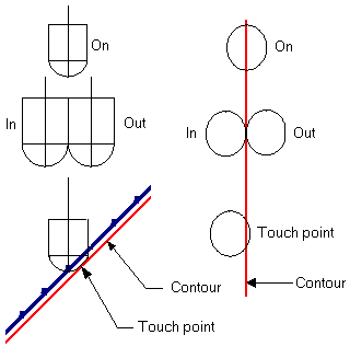
The cutter tip will be on the contour. |
||||
|
In |
The cutter will be tangent to the contour from the inner milling side. |
||||
|
Out |
The cutter will be tangent to the contour from the outer milling side |
||||
|
As Touch Point |
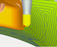
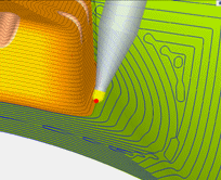
The cutter machines the part on the condition that the cutter touches the part within the specified region. The selected contour can be 2D or 3D. This boundary type limits the machining area by the touch point between the cutter and the surfaces and is most useful when machining free-form surfaces. This option is important when, for example, it is necessary to perfectly match the machining regions of two cutters with different shapes, or when the machining must completely cover, yet not exceed a specific area. In the examples below, a perfect match between two cutters that machine separate areas is achieved by using a common contour as a touch point boundary. The two images show different cutters, with the common touch point (RED point).
This option is related to Sharp Edges. When the selected boundaries are edges of part surfaces, they are considered to be sharp edges as well. The As Touch Point option is available for the procedures Surface Milling > Finish Mill All and Surface Milling > Finish By Limit Angle.
|
||||
|
Tangent |
The cutter will be tangent to the contour. The tangent side is defined by the Milling Side parameter.
|

Note: If multiple contours are selected with different Cutter Location values (i.e. one contour is defined as ON and the other contour is defined as OUT), the Cutter Location parameter (in the Boundary Settings table) will display "Multiple". If the Cutter Location values are the same for multiple contours, this value is displayed in the Cutter Location parameter.
Additional Image:Additional Image:
Plunge Mill Options
Plunge Mill procedures have the following cutter location options:
|
In |
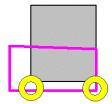
Plunging is tangent to the defined contour (from the inside), regardless of the shape of the stock. |
|
Automatic |
Plunging is either In, On or Out of the defined contour and in accordance with the shape of the stock. |
The Automatic option is calculated as follows:
|
|
|
|
|
|
If, due to a complicated 3D stock, the plunger doesn't remove material outside the contour even though it is plunging on the contour, the plunge will be allowed (as long as no material outside the contour is damaged). |
|
|
