Rounding the corners of toolpaths
Rounding the corners of toolpaths enables a smoother toolpath, which is essential for High Speed Machining (HSM).
|
Round Corners: OFF Notice the sudden motion change direction, while passing a sharp corner in the geometry. Sharp tool motions in high speed machining can cause the machine to vibrate and lead to reduced surface quality. |
Round Corners: ON Notice that the motions are now switching from the vertical area to the horizontal in a rounded manner, which is much better for high speed machining. |
One or more of the Round Corner parameters are displayed for the following procedures: See below for parameters specific to the following procedures: |
|
|
|
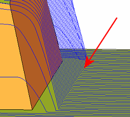
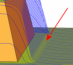
|
Round Corners |
Round the corners of toolpaths, in all areas, for High Speed Machining. Note: Round Corners will affect the final pass only. Round Connections will round the parallel lines at the edges. |
|
Preferred Corner Radius |
Set the target radius to be used for rounding the corners of the toolpath. If the Preferred Corner Radius cannot be applied as it causes an interference with the part, or removes a large portion of the original lane, reduce the radius as appropriate, up to the radius displayed in the Minimum Corner Radius parameter (see below). If the parallel optionsparallel options of Rough and Finish are selected, the rounding is done on a plane perpendicular to the XY plane. |
|
Minimum Corner Radius |
The minimum corner radius for round corners. Note: This option is not displayed when:
|
|
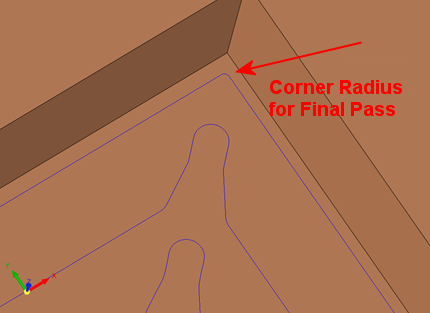
Corner Radius for Final Pass |
Set a specific corner radius for the final pass. This allows the cutter to move along a smaller round motion, thus closer to the wall.
This parameter appears in the Rough Spiral, Volume Pocket and Surface Milling (for Spiral milling) procedures. |
|
Smoothing Radius |
Smoothing Radius is a VoluMill Pocket and VoluMill Rough parameter and is similar to Minimum Corner Radius (above). See the Smoothing Radius explanation below. |
Smoothing Radius
This VoluMill Pocket and VoluMill Rough parameter is the minimum radius the tool will transverse when cutting. To machine into sharp corners or tight areas, VoluMill has to make small moves that may be more effectively accomplished using a smaller tool in a clean-up operation. The optimal, and default, Min Toolpath Radius is 45% of the tool diameter. At this value VoluMill can reach velocities that can dramatically reduce cycle times. However, it may leave areas uncut.
Using a smaller value may enable the tool to machine more material. This, however, may be less efficient than switching to a smaller tool and using another VoluMill toolpath to machine the remaining material.
The smallest value allowed is 5% of the tool diameter. VoluMill is designed to never make sharp directional changes while in the cut. This means that if your part has a fillet in the corner that is equal to the tool radius, a small amount of material will be left in the corners, even if the Smoothing Radius value is set to the minimum allowed.
Examples:Examples:
|
A large Smoothing Radius may leave uncut material: |
A small Smoothing Radius may enable the tool to machine tight areas: |
|
|
|
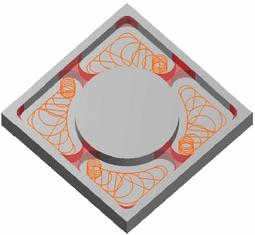
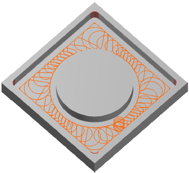
This parameter is displayed in the High Speed Machining parameter table for the VoluMill Pocket and VoluMill Rough procedures. VoluMill is a roughing technology, and it is assumed that a finish pass will follow.
Default = 45% of the tool diameter.
Minimum = 5% of the tool diameter.
Maximum = 45% of the tool diameter.
Finish by Limit Angle:
The following Round Corner parameters are displayed if Finish by Limit Angle is selected. These parameters enable you to define specific round corner values for horizontal and vertical areas:
|
Horiz. Area Round Corners |
Round the corners of toolpaths, in horizontal areas, for High Speed Machining. If this checkbox is selected, the following parameters are displayed: |
|
Horiz. Preferred Corner Radius |
Set the preferred radius of the round corners in horizontal areas. If the Horiz. Preferred Corner Radius cannot be applied as it causes an interference with the part, or removes a large portion of the original lane, reduce the radius as appropriate, up to the radius displayed in the Horiz. Minimum Corner Radius parameter (see below). Notes:
If the parallel option of Finish by Limit Angle is selected (Horiz. Machining Method = Parallel), the rounding is done on a plane perpendicular to the XY plane. |
|
Horiz. Minimum Corner Radius |
The minimum corner radius for horizontal round corners. Note: This option is not displayed in Finish by Limit Angle if the parallel option is selected (Horiz. Machining Method = Parallel). |
|
Vertical Area Round Corners |
Round the corners of toolpaths, in vertical areas, for High Speed Machining. If this checkbox is selected, the following parameter is displayed: |
|
Vertical Preferred Corner Radius |
Set the preferred radius of the round corners in vertical areas. Notes:
|
Warning: If Vertical Area Round Corners is used, in order to avoid tool breakage, use Horiz. Area Round Corners with the Horiz. Preferred Corner Radius > Vertical Preferred Corner Radius.
Cleanup Procedures:
The following rounding parameters are displayed for Cleanup, Guided Cleanup and Multi Axes Guided Cleanup.
|
Along Contours Round Corners |
Round the corners of toolpaths, in horizontal areas, for High Speed Machining. If this checkbox is selected, the following parameter is displayed: |
|
Along Contours Preferred Corner Radius |
Set the preferred radius of the round corners in horizontal areas. The Along Contours Preferred Corner Radius must be ≥ Layers Preferred Corner Radius. |
|
Layers Round Corners |
Round the corners of toolpaths, in vertical areas, for High Speed Machining. If this checkbox is selected, the following parameter is displayed: |
|
Layers Preferred Corner Radius |
Set the preferred radius of the round corners in vertical areas. Default = 0.05*tldi + 0.2. The Layers Preferred Corner Radius must be ≤ Along Contours Preferred Corner Radius. |
If the Round Corners and the ReRough (in Tool Trajectory) options are both ON, a warning is issued to the Output dialog that the round corners are not implemented for the ReRough milling.