|
Layers
|
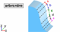
Machine the vertical areas using Layers machining technology. This is used for removing material for vertical or nearly vertical walls. The motions are horizontal along the machined wall.
When Layers technology is selected, the parameter Min. Corner Feed is displayed in the Machine Parameters.
Image:Image:
When Layers technology is selected, the following checkbox parameter is displayed:
|
Variable Vertical Step
|
When this checkbox is marked  ,
then machine the vertical areas using Variable Layers machining technology.
This is used for removing material for vertical or nearly vertical walls.
The motions are horizontal along the machined wall. This differs from
the Layers technology in that the density of the layers can be controlled
using the Vert. Max. Scallop parameter. ,
then machine the vertical areas using Variable Layers machining technology.
This is used for removing material for vertical or nearly vertical walls.
The motions are horizontal along the machined wall. This differs from
the Layers technology in that the density of the layers can be controlled
using the Vert. Max. Scallop parameter.
Default = OFF 
Image:Image:
|
|
|
Helical
|
Machine the vertical areas using Helical motions.
The Helical milling strategy is useful for milling all around steep cavities or cores, especially in electrodes.
Helical milling produces a continuous toolpath with only one entry and exit point. Helical milling thus offers surface quality advantages and also achieves a shorter machining time.
Image:Image:
There is only one entry and one exit point on all the closed "layers", resulting in a better surface quality.
When Helical technology is selected, the following checkbox parameters are displayed:
|
Variable Vertical Step
|
When this checkbox is marked ,
then machine the vertical areas using Variable Layers machining technology.
This is used for removing material for vertical or nearly vertical walls.
The motions are horizontal along the machined wall. This differs from
the Layers technology in that the density of the layers can be controlled
using the Vert. Max. Scallop parameter.
Default = OFF
Image:Image:
|
|
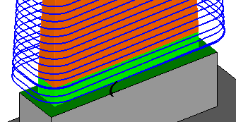
Complete First and Last Passes
|
When this checkbox is marked ,
create additional milling layers for the helical motions, to ensure zero
left over material.
For Complete First and Last Passes,
the milling layers are created at the top and bottom of the helical motions.
For Complete Last Pass, the milling
layer is created at the bottom of the helical motions.
Default = ON  . .
Image:Image:
In this example, an additional
milling layer ensures zero left over material at the bottom of the
helical motions.
|
|
|
Bumping
|
Machine the vertical areas using Bumping machining technology. The Bumping Direction parameter is displayed, with the following dropdown options:
|
Down
|
Machine the vertical areas using Bumping machining technology. This is used mainly for semi-finish operations for quickly removing material using vertical motions. In this case, the cutter only moves down, from the top to the bottom.
This is the default bumping option.
Image:Image:
|
|
Up
|
Machine the vertical areas using Bumping machining technology. This is used mainly for semi-finish operations for quickly removing material using vertical motions. In this case, cutter only moves up, from the bottom to the top.
Image:Image:
|
|
Bidir
|
Machine the vertical areas using Bumping machining technology. This is used mainly for semi-finish operations for quickly removing material using vertical motions. In this case, cutter moves in both up and down directions.
Image:Image:
|
|