|
|
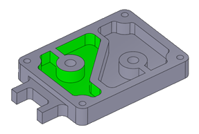
Pocket Output Geometry for Downstreaming
Recognition of all pockets in a Plate is a preliminary step for automating the process of pocket machining.
The recognized pockets can be used in downstream procedures and templates. The relevant geometry from the Pocket feature is automatically selected by the procedure. For example, the Volume Pocket procedure takes the pocket’s volume, the Finish procedures take the surfaces and the Profile procedures (Profile Closed Contour and Profile Open Contour) take the contours and Z values.
The following pocket geometry output rules apply.
-
When using procedures, the output from a pocket may be:
-
Its volume.
-
Its surfaces.
-
Its contours and their numeric values (as boundaries).
-
-
When pockets are selected By NC Pockets from the Contour Manager, only contours with their numeric values (heights) are output from the pocket.
-
When pockets are selected by Pockets in the Geometry parameters table, the output depends on the procedure type:
-
Rough Spiral, Rough Parallel, Volume Pocket:
-
The surfaces of selected pockets are used as part surfaces (group one).
- The volumes of selected pockets are used as Stock.
-
The contours are not used.
-
Safe Milling and Stock work in a similar way to Volume Pocket.
-
Surfaces and Contours that are selected directly (by criteria or manually) are used.
-
-
Finish, Cleanup, Rest Milling and Pencil:
-
The surfaces of selected pockets are used as part surfaces (group one).
-
These surfaces (from pockets) create Automatic Boundaries with default settings.
-
The volumes of selected pockets are not used.
-
The contours are not used.
-
Safe Milling and Stock work normally.
-
|