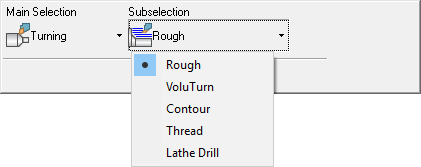
Turning
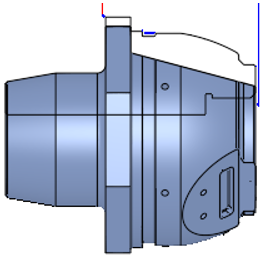
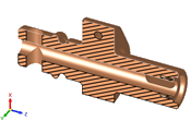
Turning is a material removal process to create rotational parts on a turning machine or lathe.
The Turning procedures support milling and turning together, on Mill-Turn machines and milling machines with turning capabilities. The system supports 2-axis machining with full functionality for roughing, high-speed roughing, contouring, threading, center drilling, tapping and boring.
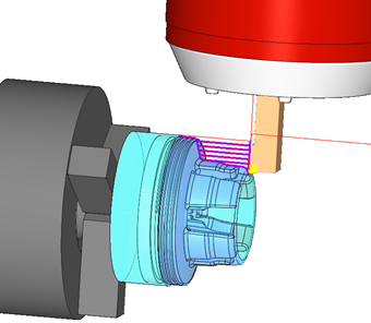
In Turning, the workpiece is placed on a spindle spinning around the Z-axis of the reference UCS, which is defined in the NC Setup. The tool, which is not spinning during the procedure, can be positioned in any fixed orientation within the work envelope of the 5X machine, including a different orientation around the tool's axis.
The Turning procedures are integrated into the entire NC process, and can be combined with milling and drilling procedures. The stock is updated throughout the process both for milling and turning.
A Lathe Views toolbar is available specifically for the Turning procedures, with options to control the view of the turning part on the turning plane (ZX). See Lathe Views Toolbar, below.
Turning Technologies
Cimatron supports a variety of Turning procedures. It is possible to define outside and inside diameter cutting as well as front and back facing. You can define toolpaths in a way that the tool cuts in both, forward and reverse directions or in one direction only.
The following Turning technologies are available in Cimatron:
|
Turning procedures |
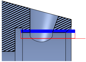
Contour |
Take a single turning pass along a shape, creating a smooth surface
finish.
Used for finishing operations. |
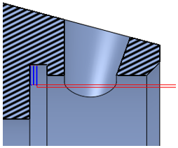
| Groove |
Create geometry-independent rectangular grooves.
Used for predefined groove cycles. |
|
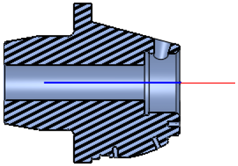
| Lathe Drill |
Create a hole in the center of the turning material.
Used for center holes (X0, Y0 coordinates). |
|
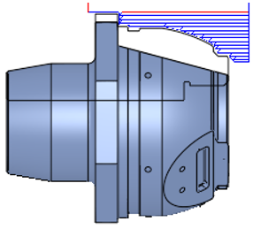
| Rough |
Remove turning material using multiple passes on a shape. Various technologies
are available, such as turning, pattern offsets or plunging.
|
|
| Thread |
Create a thread on the outside or inside diameter of the turning material.
Used for lathe threading. |
|
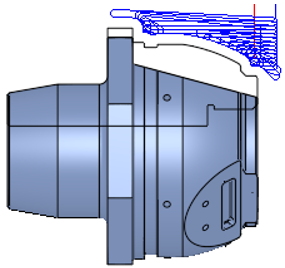
| VoluTurn |
Remove turning material using a cutter with a round insert. Smooth flowing
motions are created that evenly distribute wear on tool inserts. VoluTurn
is particularly well-suited to machining tough materials such as titanium
and hardened steels.
Used for high-speed roughing using a round insert. |
|
|
|
|
|
|
Turning > Rough |
Turning > VoluTurn |
Turning > Contour |
|
|
|
|
|
Turning > Thread |
Turning > Lathe Drill |
Turning > Groove |
Workflow
The workflow for NC Technologies consists of the following steps:
- Machine Definition. More:More:
This application enables you to construct a machine definition for the Machine Simulator. It enables defining the kinematics tree structure, the axes, and the displayed components of the CNC machine. This enables you to simulate the G-Code motions on a virtual machine that imitates the real machine behavior.
Important! This application is for use by qualified personnel only. Contact your Cimatron Provider or Reseller to get a machine definition for the Machine Simulator.
Configure the turning (lathe) machine parameters and create the saved file as a Machine Definition Document (MDD) file. The MDD is a prerequisite for enabling turning operations.
- NC Setup and Configuration. More:More:
The NC Setup enables you to predefine multiple project-related options in a single place. The NC Setup contains the general data associated with a project, such as the part material, part geometry, machining orientations, fixtures, initial stock, machine name, and post processor. The data defined in the NC Setup is later used as the default for various NC operations. For example, the defined part material is used to set different machining parameters in the cutter definition. The NC Setup parameters can be edited as required.
Define the machine and the Turning configuration prior to creating a Turning cutter or procedure. The Turning configuration and related parameters are specified in the NC Setup. This associates the Machine Definition Document (MDD) created during the Machine Definition process, with the Machine type currently specified in the NC Setup dialog. The MDD is a prerequisite for enabling turning operations.
- Stock definition and update. More:More:
Stock is a 3X procedure used to represent the stock material from which the final part will be produced. Remaining stock is calculated after each procedure so that cutter motions can be optimized upon the current stock status. Stock is also used by the Simulator and Verifier. The remaining stock can be displayed at any time after any executed procedure (the procedure must have a  status flag).
Define the stock using the Stock Revolve option.
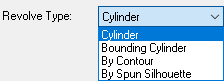
The following types of stock revolve definitions are available:
|
|
- Cylinder |
The Turning rough procedures take into consideration the remaining stock before the procedure in order to create an easy and efficient Turning toolpath. The stock model is fully updated throughout the process, both for Turning and Milling procedures.
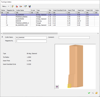
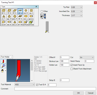
- Cutters definition. More:More:
Select a cutter for a turning procedure; define cutters and set the parameter defaults for specific cutters.
For creating a new Turning cutter, or editing an existing one, an edit dialog is used. The system supports a wide variety of predefined common tool shapes, as well as user-defined form tools.
Example:Example:
- Procedure selection. More:More:
Create a Procedure in the active toolpath. A Procedure is a set of cutter movements that conform to a specific machining technology. One or several Procedures can comprise a toolpath.
See Technologies, below.
- Geometry definition. More:More:
The Geometry Parameters define the geometrical entities to be used during the procedure operation.
A Spun Silhouette contour creation option is available in the NC Contour Manager, to enable fast and easy programming of Turning procedures. The geometry is selected in the Cimatron graphics window using the NC Contour Manager, enabling you to control the initial starting point and the end-point of the contour machining.
- Review and output of the toolpath. More:More:
Once the toolpath is created and the procedure has been executed, perform operations on the toolpath to display and analyze the toolpath or edit cutter motions (Navigator, Global Filter, Motion Editor).
The Machining Simulation tools offer a combined environment for machining simulation that includes the following capabilities: material removal simulation, machine simulation, and verifier. These tools enable you to simulate and verify your NC toolpaths and procedures before implementing them on the shop floor.
- Report. More:More:
The NC Report is a file that provides various information about a set of selected procedures. This information includes details about the project and provider, as well as toolpaths, procedures (including multi-cutter information), and parameters.
A Cimatron Post Processor is a program that translates Cimatron NC (Numerical Control) data (toolpaths and procedures) into specific CNCCNC machine tool commands (machine code). These commands are known as Posts or G-Code programs (see the Glossary for additional information on G-Code).
Important: This application is for the use of qualified personnel only. Contact your Cimatron Provider or Reseller to create the appropriate G-Code.
Important: This application is for the use of qualified personnel only. Contact your Cimatron Provider or Reseller to create the appropriate G-Code.
Important: This application is for the use of qualified personnel only. Contact your Cimatron Provider or Reseller to create the appropriate G-Code.
Lathe Views Toolbar
For NC files, additional view options are displayed, specifically for Turning (Lathe) operations but available for all NC files. These view options are displayed in the View > Views section of the main menu and also on the Lathe Views toolbar, enabling you to control the view of the part on the Turning plane (ZX). The following Lathe view options are available:
|
Lathe Views toolbar |
View>Views main menu |
||
|
|
|
Lathe Isometric View |
Rotate to the Lathe Isometric view of the turning plane (ZX) and apply Zoom All (zoom to the entire window).
|
|
|
Lathe Front View |
Rotate to the Lathe Front view of the turning plane (ZX) and apply Zoom All (zoom to the entire window).
|
|
|
|
Lathe Section View |
Lathe Section view of the part and stock on the turning plane (ZX). |
|


|
Lathe Isometric View |
Lathe Front View |
Lathe Section View |
|
|
|
|

Notes:
-
When the Lathe Section View is ON, this displays a dynamic section in the XZ plane with Y=0, but without the Dynamic Section function dialog. The section direction (+Y or -Y) is according to the current view.
-
If the Lathe Section View is ON and you invoke the Dynamic Section function (or vice versa):
-
The parameters in the Dynamic Section function dialog will be updated with the Lathe Section View values (XZ plane, with Y=0, +Y/-Y according to current view).
-
The Lathe Section View button remains ON.
-
-
This functionality is license dependent; it is available if you have the appropriate license. Contact your Reseller if you require this functionality.