|
|
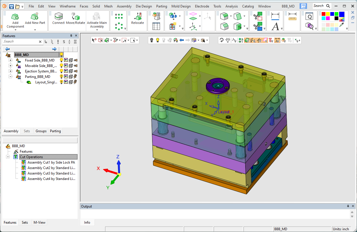
Assembly Environment Interface
When an assembly is opened or created, it is loaded into a window in the Assembly environment. The Assembly environment is divided into two main areas: the Tree Pane and the graphics area (Graphics Pane).
The Tree Pane consists of two trees:
-
Assembly Tree (upper) lists the assembly components and constraints.
-
Feature Tree (lower) lists the assembly operations and features. In addition, the Feature tree also lists all the features associated with an active part (the same features as those displayed in the Part environment for a specific part).
The Assembly environment includes the Assembly, Die Design, Parting, Electrode, and Mold Design functions. Toolbars are displayed on top and to the right of the graphics area.
Click on an item in the dialog for a description.
Assembly Environment Usage
The Assembly environment is used to apply constraints between existing parts that represent physical relationships in the real world; the end result being an assembly that acts and looks like a final product.
Components can be added, positioned, or removed from the assembly as required.
Interferences between components can also be checked. In the Die Design, Parting, Mold Design, and Electrode assembly environments, additional tools enable you to set attributes to specific components, thereby defining their usage. For example, a cooling or lifter item in Mold Design or a blank or burn body in Electrodes.
|