|
|
Model/CAD Terms
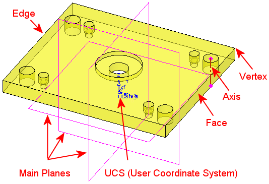
The following model terms are used throughout this Help. They refer to geometric elements in a model, such as faces, edges, and vertices as well as construction geometry, such as reference planes, axes, and the UCS (User Coordinate System).
|
|
A Plane (or reference plane) is used as a reference and basis for other actions. The initial reference plane is the XY plane. A reference plane may either be one of the three main (Cartesian) planes (XY, YZ, ZX), or it may be a custom user-defined plane. A Vertex is a point where two or more curves, lines, or edges meet. An Edge is a line that joins two vertices. An edge can also be the boundary of a shape. For example, a circle. An Axis is a straight line on which an object may rotate or that divides an object into symmetrical halves. A UCS (User Coordinate System) is used for orientation to define direction and many other operations. |
Other CAD Terms
|
B-rep |
B-rep or BREP (Boundary Representation) is a method for representing shapes using boundary limits. B-rep models are composed of topology (faces, edges, and vertices) and geometry (surfaces, curves, and points). A face is a bounded portion of a surface; an edge is a bounded piece of a curve; and a vertex lies at a point. There are other elements, such as a shell (a set of connected faces) and a loop (a circuit of edges bounding a face). |
|
Mesh |
A Mesh model consists of vertices, edges, and faces to create a series of planar regions called facets. These facets are polygons, including triangles and quadrilaterals, used to define a 3D shape. The process of creating a mesh is called tessellation. Once tessellated, the mesh can be subjected to simulated stresses, strains, temperature differences, etc. for FEA (Finite Element Analysis). |
|
Surface |
Regular surfaces include surfaces of revolution such as cylinders, cones, spheres, tori, and ruled surfaces (linear in one direction), such as surfaces of extrusion. |
|
Wireframe |
A Wireframe represents a surface as a series of lines and curves. The advantage of this representation is that a great deal of geometry may be displayed and rotated on the screen with no delay needed for graphics processing. |
|
Solid |
A Solid is represented as a collection of connected surface elements; the boundary between solid and non-solid. |
|
Point Cloud |
A Point Cloud is a set of data points in a coordinate system. |
|
Facet |
A Facet is typically a flat three or four-sided polygon that represents an element of a 3D polygonal mesh surface or model. Multiple facets create a series of planer regions on the mesh surface or model. In Cimatron, facets are usually triangular. |
|