|
|
ROT_MAT and ORIGIN CHANGE - Upgrading 4X to New ROTMAC
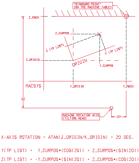
In previous versions of the GPP, the toolpath origin had to be located in the rotation axis and the coordinates were rotated before being sent to the post processor. Therefore, old post processors could handle any rotation or translation problems.
In order to prevent major changes in the original post processors, new toolpaths should be created carefully. This is done as follows:
-
Locate the toolpath origin in the rotation axis (as in previous versions).
-
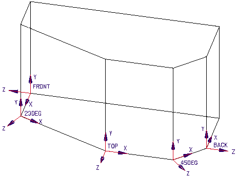
Using ROTMAC, define all the origins in the same location as the toolpath origin (rotation only, no translation).
Changing the EXF
-
Initialize the UNIT matrix and the translation values at BEGINNING OF TAPE.
-
Add the block ORIGIN CHANGE with ROT_MAT1 . . . ROT_MAT9 definitions according to the relevant rotation axis.
-
There is no need to define the TRANS_MAT parameters every origin change. They remain 0.


Post Processor ROTMAC
*
* 4-axis (tilting table) machine
* The rotation axis is: "Y".
*
* The FORMAT of parameters that are used in calculations, are redefined
* as "REAL/USER_10". The COORDINATE format is used for output only.
*
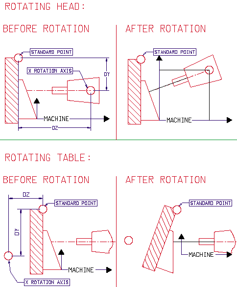
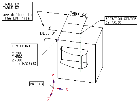
* In the POST interaction, the IND. MACHINE ZERO point is the
* red circle on the top/left corner of the machine table
* X=100.000, Y=...., Z=200.000
*
*REAL -> format (3.5) for positioning parameters
*USER_10 -> format (1.7) for I,J,K_ORIGIN and SIN,COS results.
*USER_1 -> INTEGER format for flags.
*
* Flags:
*
* FLAGROTMAC = 1 -> ROT MAC ;
* = 0 -> ORIGIN CHANGE ONLY (no ROT MAC) ;
*
* FLAGEFIRSTORIGIN = 1 -> the current ORIGIN is the first origin in the TAPE
*
*=============================================================================
FORMAT (USER_10) I_ORIGIN J_ORIGIN K_ORIGIN ;
FORMAT (USER_10) ORIGOLDI ORIGOLDJ ORIGOLDK ;
FORMAT (USER_10) COSY SINY EPS;
FORMAT (USER_10) ROT_MAT1 ROT_MAT2 ROT_MAT3 ROT_MAT4 ROT_MAT5 ;
FORMAT (USER_10) ROT_MAT6 ROT_MAT7 ROT_MAT8 ROT_MAT9 ;
FORMAT (REAL) TRANS_MATX TRANS_MATY TRANS_MATZ ;
FORMAT (REAL) X_ORIGIN Y_ORIGIN Z_ORIGIN ;
FORMAT (REAL) X_HOME Y_HOME Z_HOME ;
FORMAT (REAL) FIRSTORIGINX FIRSTORIGINY FIRSTORIGINZ ;
FORMAT (REAL) YROTATION ;
FORMAT (REAL) H V A ;
* In the case of a rotating table machine
FORMAT (REAL) TABLEDX TABLEDZ;
FORMAT (REAL) TOTALDX TOTALDZ;
FORMAT (REAL) TOTALAFTERROTX TOTALAFTERROTZ;
FORMAT (REAL) DELTAORIGINX DELTAORIGINY DELTAORIGINZ ;
FORMAT (REAL) DELTAFIRSTX DELTAFIRSTY DELTAFIRSTZ ;
* Output format
FORMAT (COORDINATES) XOUT YOUT ZOUT ROUT;
FORMAT (ANGLES) BOUT ;
* Flags:
FORMAT (USER_1) FLAGROTMAC FLAGEFIRSTORIGIN ;
* Constants
FORMAT (USER_10) VERTICAL ;
* INTERACTION ------------------------
INTERACTION (CHARACTER) "CIRCLES " CIRCFLAG = "N";
* ----------------------------------
NON_MODAL ALL_VAR;
MODAL FLAGROTMAC ;
NEW_LINE_IS $ ;
OUTPUT \J ".. " ;
BEGINNING OF TAPE:
*-Distance between the FIX point on the machine table and the
* rotation center
TABLEDX = 250; TABLEDZ = -200;
FLAGROTMAC = 1;
FLAGEFIRSTORIGIN = 1;
VERTICAL = 1.0;
*-For the first origin change
ORIGOLDI=0; ORIGOLDJ=0; ORIGOLDK=1.0;
*-Unit matrix (MUST be input in this order !!!)
ROT_MAT1 = 1; ROT_MAT2 = 0; ROT_MAT3 = 0;
ROT_MAT4 = 0; ROT_MAT5 = 1; ROT_MAT6 = 0;
ROT_MAT7 = 0; ROT_MAT8 = 0; ROT_MAT9 = 1;
TRANS_MATX = 0; TRANS_MATY = 0; TRANS_MATZ = 0;
output \J "This post processor is a demo for a 4-axis machine";
output \J " with a rotating table around the 'Y' axis.";
output \J "The output is expressed in each origin coordinate system,";
output \J "however the changes to be done in order to use only one origin";
output \J " are explained in the Post Processor EXF file.";
output \J " ";
output \J " ";
output \J "part file: " PART_NAME ;
output \J " ";
output \J "machine parameters:" ;
output \J " machine type : ROTATING TABLE ";
output \J " distance from the standard point on the ";
output \J " machine table to the rotation point (X,Z) = " TABLEDX ", " TABLEDZ ;
output \J " standard point location according to the MACSYS: " X_MACH " " Y_MACH " " Z_MACH ;
output \J " ";
output \J "number of origins in the tape: " NUM_ORIGS ;
output \J " ";
output \J " ";
print \j "part file: " PART_NAME ;
IF_SET (CIRCFLAG _EQ_ "N") print \j "no circles"; end_if;
END OF TAPE:
output \J " ";
output \J "end of tape";
BEGINNING OF PROC:
output $ "************************************************* ";
output $ "(PROC: " PROC_NAME " " MOVMNT_NUM " MOVMENTS)";
ORIGIN CHANGE:
output \j " ";
output \j " origin = " curr_orig;
output \j " i = " i_origin ;
output \j " k = " k_origin ;
*--Output circular motion as string of linear motions in case K_ORIGIN 1 and
* the flag CIRC is "N"
* Normally, a rotating table 4-axis machine can perform circular motion
* at any angle.
IF_SET (K_ORIGIN _NE_ VERTICAL)
IF_SET (CIRCFLAG _EQ_ "N")
SET_OFF CIR_INTERP ;
ELSE
SET_ON CIR_INTERP ;
END_IF;
END_IF ;
*-Save the first origin data for later use
* in the case of "one origin output"
IF_SET (FLAGEFIRSTORIGIN _EQ_ 1)
FIRSTORIGINX = X_ORIGIN;
FIRSTORIGINY = Y_ORIGIN;
FIRSTORIGINZ = Z_ORIGIN;
FLAGEFIRSTORIGIN = 0;
END_IF;
*-check if the new ORIGIN has a different ORIENTATION than the previous
* one
SET_OFF FLAGROTMAC ;
IF_SET (I_ORIGIN _NE_ ORIGOLDI) SET_ON FLAGROTMAC; END_IF;
IF_SET (J_ORIGIN _NE_ ORIGOLDJ) SET_ON FLAGROTMAC; END_IF;
IF_SET (K_ORIGIN _NE_ ORIGOLDK) SET_ON FLAGROTMAC; END_IF;
*-Save the orientation of the current origin
ORIGOLDI=I_ORIGIN;
ORIGOLDJ=J_ORIGIN;
ORIGOLDK=K_ORIGIN;
*-ROTMAC - change the tool orientation
IF_SET(FLAGROTMAC)
*-Calculate the rotation angle of the Y axis.
V=I_ORIGIN; H=K_ORIGIN;
CALL "ATANG2" INPAR V H; OUTPAR A;
YROTATION = A;
COSY = COS(YROTATION); SINY = SIN(YROTATION);
output \j " angle = " yrotation;
*-Calculate the ROT_MAT values for the rotating table machine
ROT_MAT1 = COSY ; ROT_MAT2 = 0 ; ROT_MAT3 = -SINY ;
ROT_MAT4 = 0 ; ROT_MAT5 = 1 ; ROT_MAT6 = 0 ;
ROT_MAT7 = SINY ; ROT_MAT8 = 0 ; ROT_MAT9 = COSY ;
output \j "matrix:" ;
output \j " " ROT_MAT1 " " ROT_MAT2 " " ROT_MAT3 ;
output \j " " ROT_MAT4 " " ROT_MAT5 " " ROT_MAT6 ;
output \j " " ROT_MAT7 " " ROT_MAT8 " " ROT_MAT9 ;
*-Calculate the TRANS_MAT values for the rotating table machine
* only in the case of one origin output (when the other origins are
* translated from the first one), otherwise, the TRANS_MAT values
* remain "0".
*.....distance between the rotation center and the ORIGIN
TOTALDX = X_ORIGIN - X_MACH - TABLEDX;
TOTALDZ = Z_ORIGIN - Z_MACH - TABLEDZ;
*.....distance between the rotation center and the ORIGIN
* after the rotation
TOTALAFTERROTX = TOTALDX*ROT_MAT1 + TOTALDZ*ROT_MAT3;
TOTALAFTERROTZ = TOTALDX*ROT_MAT7 + TOTALDZ*ROT_MAT9;
output \j " ";
output \j "distance between the current origin and the rotating center:";
output \j "delta x: " TOTALAFTERROTX " delta z: " TOTALAFTERROTZ;
*.....distance between the ORIGIN and the new position of the ORIGIN
* after the rotation
DELTAORIGINX = TOTALAFTERROTX - TOTALDX;
DELTAORIGINY = 0;
DELTAORIGINZ = TOTALAFTERROTZ - TOTALDZ;
*.....calculate the distance between the ORIGIN and the FIRST ORIGIN.
* In the case of MULTIORIGINS output, the parameters may be used
* to calculate the MACHINE position of each ORIGIN related to the
* first one. In the case of ONEORIGIN output, TRANS_MAT parameters
* should get the values of DELTAFIRSTX..DELTAFIRSTZ.
DELTAFIRSTX = DELTAORIGINX + (X_ORIGIN - FIRSTORIGINX);
DELTAFIRSTY = DELTAORIGINY + (Y_ORIGIN - FIRSTORIGINY);
DELTAFIRSTZ = DELTAORIGINZ + (Z_ORIGIN - FIRSTORIGINZ);
output \j " ";
output \j "distance between the current origin and the first origin:" ;
output \j "delta x: " DELTAFIRSTX " delta z: " DELTAFIRSTZ ;
ELSE
*-origin change without rotation.
* In the case of ONEORIGIN output, TRANS_MAT parameters should get
* the values of DELTAFIRSTX..DELTAFIRSTZ.
DELTAFIRSTX = X_ORIGIN - FIRSTORIGINX;
DELTAFIRSTY = Y_ORIGIN - FIRSTORIGINY;
DELTAFIRSTZ = Z_ORIGIN - FIRSTORIGINZ;
END_IF;
output \j "--------------------------------";
LINEAR MOTION:
XOUT = X_CURPOS;
YOUT = Y_CURPOS;
ZOUT = Z_CURPOS;
OUTPUT $ " " LIN_MOV " X" XOUT " Y" YOUT " Z" ZOUT ;
CIRCULAR MOTION:
XOUT = X_ENDPT;
YOUT = Y_ENDPT;
ZOUT = Z_ENDPT;
OUTPUT $ " " CIRC_MOV " X" XOUT " Y" YOUT " Z" ZOUT ;
XOUT = X_CENTER;
YOUT = Y_CENTER;
ZOUT = Z_CENTER;
ROUT = RADIUS_;
OUTPUT " XC" XOUT " YC" YOUT " ZC" ZOUT " R" ROUT " " ARC_ANG " Deg.";


|