Setup – Mold Layout Tab: Mold Project 

Access: Open this function from one of the following locations:
-
Select Tools > Main Tools > Setup from the menu bar.
-
Select Die Design > Tools > Setup from the menu bar.
-
Select Mold Design > Tools > Setup from the menu bar.
-
Select Setup from the Mold Design Guide Toolbar, Parting Guide Toolbar or one of the various Die Design Guide Toolbars).
Setup parameters are those that are significant for various aspects of a project design. They represent geometrical features of the model being designed as well as parameters that influence that design. Each parameter can be assigned a value, and the dimension related to this parameter is updated accordingly. These parameters are displayed in a Setup dialog.
The Setup dialog table displays the entire set of data used in the setup of a Part or Assembly project; these parameters are used in the Part and Assembly environments (assembly includes all assembly projects – plain Assembly, Mold, and Die projects).
See Tabs usage for which tabs in the Setup dialog are relevant for each type of project.
The table of user-defined parameters is available in the General tab of the Setup dialog. Use this table to predefine various parameters used for creating relations.
Tabs in the Setup dialog
- General - Part/Assembly
- Strip Layout - Die projects
- Punch - Die projects
- Mold Layout - Mold projects
See Setup dialog description for more on the common elements in all the tabs.
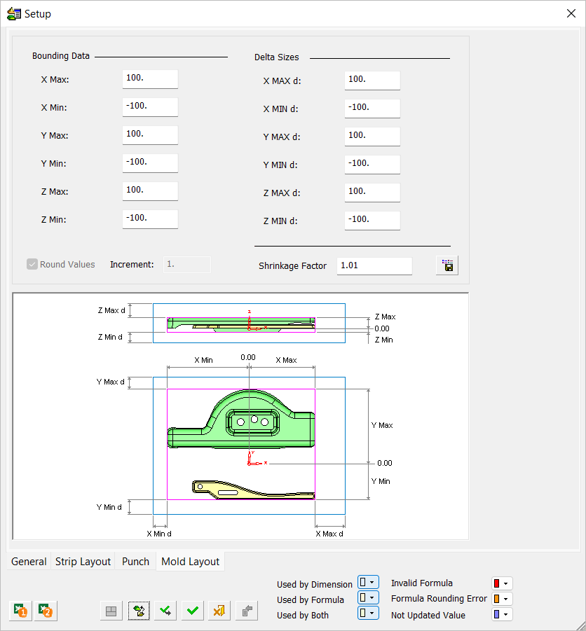
Mold Layout tabThis image shows the Mold Layout tab. |
|
|
|
|
Defining the Mold Setup parameters
-
Load the Mold file for which you want to define and view the Mold Setup.
-
LaunchLaunch the Mold Setup function.
-
Set the parameters using this section as a guide. The elements that make up the Mold Layout tab are described in this section, the links below link to each description.
- Bounding Data
- Delta Sizes
- Shrinkage Factor
Bounding Data
This section holds the bounding data of the work parts. The box binds all the components marked and recognized as work parts, including all of their geometry.
|
|
|
Notes:
-
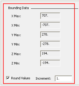
If there are one or more work parts, these parameters are filled automatically (derived from the work parts size) and not editable. You can Round the values by setting an Increment. The Round and Increment parameters are only available when there is at least one work part.
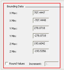
ExamplesExamplesWork part bounding data
Parameters Rounded
-
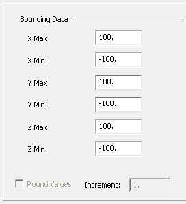
If there are no work parts:
-
-
All Max parameters are all set 100mm or 5 inches
-
All Min parameters are all set -100mm or -5 inches
-
All parameters are open for writing.
-
The Round and Increment parameters are dimmed.
-
|
No work part—default values—No Rounding |
|
|
Delta Sizes
This section holds parameters that only operate as fixed names to be used in formulas. Any numeric value can be entered here including negative values.
| Default Delta Size values | |
| File Type | Value |
| mm file | 100 |
| inch file | 5 |
These parameters do not interact with the Rounding mechanism.
|
|
|
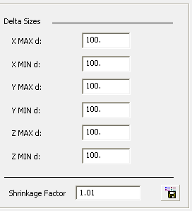
Note: The Delta Sizes values can be overridden using the Load Setup dialog (see Load Setup button).
Shrinkage Factor
The Shrinkage Factor field displays the value in the Load Work Parts dialog and can be changed as required. This value must be positive.