Cutters Dialog: Turning Tool Options 

Access: Open this function from one of the following locations:
In the Turning Cutters dialog:
-
Select the New Cutter icon
 .
. -
Select the Edit Selected Cutter icon
 .
. -
Double-click a cutter row to edit the selected cutter.
In the Turning Cutter Definition dialog, define the tool holder options of the selected insert type.
Example dialogExample dialog
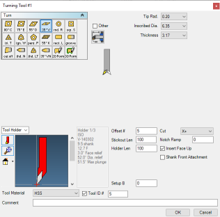
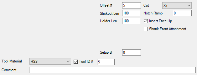
Parameters
|
Spindle Direction Forward/Reverse |
Forward will turn the spindle in the forward or normal direction. Selecting Reverse will reverse the spindle. |
|||||||||||||||
|
Offset # |
The register number for the tool radius in the machine. Normally, the Offset Number of the tool is determined by its location in the Tool List. The Offset # parameter enables you to override that default with a different number. |
|||||||||||||||
|
Stickout Length |
Distance from the holder to the contact tip. |
|||||||||||||||
|
Holder Length |
The length of the insert holder. |
|||||||||||||||
|
Cut |
Choose from the dropdown to either cut on the X- or X+ side. |
|||||||||||||||
|
Notch Ramp |
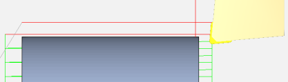
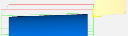
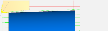
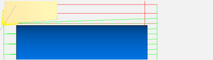
Ramping is a tool entry method whereby the tool enters the part by gradually increasing in depth, preventing any shock loading on the tool to avoid poor tool life or premature tool failure. The angle of entry is determined by a defined ramp angle. Notch Ramping means that the toolpath will be created by adding the Notch Ramp value to alternating strokes: one with, one without. In Roughing Operations, this will reduce the depth of cut on one stroke and increase it on the next. Ensure that the ramp value is smaller than the depth of cut. Notch Ramp is not available for Groove, Cut Off, or Thread tools. A negative notch ramp value creates a positive X+ angled cut (angled upwards), while a positive value creates an X- angled cut (angled downwards). Notch Ramping uses more of the insert surface to cut the material by taking angled (ramp) cuts followed by straight cuts (cuts are alternately angled then normal). Following an angled cut, the straight cut removes material to produce a horizontal cut.
This strategy prevents notches wearing into the tool by allowing the contact point to move across the tool so that the tool doesn't wear out in a single location. |
|||||||||||||||
|
Insert Face Up |
When this checkbox is ON |
|||||||||||||||
|
Shank Front Attachment |
When this checkbox is OFF |
|||||||||||||||
|
Setup B |
Touch-off angle of the tool tip when setting up offsets. |
|||||||||||||||
|
Tool Material |
This is a dropdown list used to specify the material of the tool. The information given here is used by the Material Database as another factor in determining speeds and feeds. The default setting for Lathe parts is Carbide Insert, Coated. |
|||||||||||||||
|
Tool ID # |
When this checkbox is ON |
|||||||||||||||
|
Comment |
This is a comment associated with the tool. This comment will be output in the finished code (in brackets) at the beginning of every operation that uses this tool. |