Cutters and Holders: Multiple Cutters

Access: Open this function from the following location:
Define multiple cutters that enable you to use a sequence of milling cutters in one procedure. This parameter enables you to:
|
Use Multiple Cutters OFF |
Use Multiple Cutters ON |
|
|
|
|
When the Use Multiple Cutters checkbox is ON
|
Notes:
-
The Use Multiple Cutters checkbox parameter is displayed in the following procedures: Finish, Cleanup, Pencil, and the following Volume Milling (Rough) procedures: Rough Parallel, Rough Spiral, and Volume Pocket.
-
When using multiple cutters in the Rough procedures, an additional parameter is displayed in the Tool Trajectory parameter table to optimize the procedure: Optimize By.
-
The Use Multiple Cutters parameter will only be displayed if the initial cutter has a defined holder.
-
To use multiple cutters in a procedure, all the cutters must be of the same type (Ball End, Flat End, and so on) and the same diameter as the initial cutter. Each cutter must also have a defined holder.
-
When the Use Multiple Cutters checkbox is ON
 , additional parameters are displayed in the parameter table. The parameters that are displayed depend upon which procedure you are running and other parameters you have defined elsewhere (for example Bumping Up or Variable Layers in the Vert. Machining Method in the Tool Trajectory parameter table).
Parameter Table Branch
Parameters added to the table
Cutters & Holders
Horiz. Step and Down Step
(moved from the Tool Trajectory parameter table)Feed and Spin Calculator
(moved from the Machine Parameters parameter table)Tool Trajectory
Horiz. Cutters Overlap
(in Finish and Cleanup functions)Vert. Cutters Overlap
(in Finish and Cleanup functions)Cutters Overlap
(in the Pencil function) -
A different Horiz. Step and Down Step can be defined for each of the used cutters.
-
Cutter parameters cannot be changed from the Multiple Cutters Selection dialog. All the parameter fields in this dialog are disabled.
-
When the Use Multiple Cutters parameter is ON
, you will still be able to create new cutters using the Cutter option from the NC Guide. -
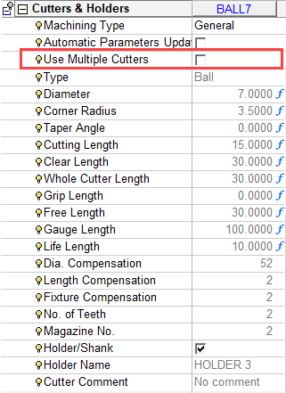
If the Use Multiple Cutters parameter is OFF
 , the main cutter button in the Cutters & Holders parameter table will revert back to displaying the main cutter name.
 -
After creating new cutters that meet the multiple cutter criteria (they must all be of the same type and diameter as the initially selected cutter and must all have a holders defined for them), these new cutters will appear in the Cutters List dropdown menu under the Cutters & Holders parameter table.
-
If a new procedure is created after using the multiple cutters option, the whole set of previously selected cutters will be included into the new procedure.
-
If a procedure contains multiple cutters, this procedure can be divided into a number of separate procedures, each of which uses only one cutter.
Defining multiple cutters in a procedure
-
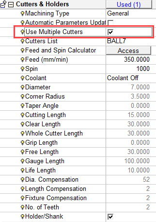
Select the Use Multiple Cutters parameter, under Cutters & Holders within the Procedure.
The following changes occur in the parameter list:
-
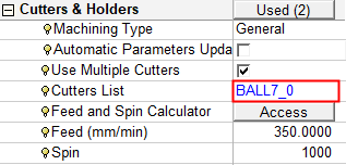
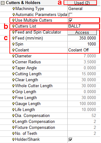
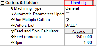
The number of cutters defined for the current procedure is displayed. Initially, there is only one.
-
The current cutter name is displayed (BALL7).
-
Additional parameters are displayed under the Cutters & Holders parameter table. The parameters that are displayed depend on which other parameters you have defined (for example Bumping Up or Variable Layers in the Vert. Machining Method). These parameters are moved from their original locations in the procedure parameter tables. The following parameters are displayed:
-
Horiz. Step and Down Step (moved from the Tool Trajectory parameter table).
-
Feed and Spin Calculator (moved from the Machine Parameters parameter table).
-
Feed and Spin (moved from the Machine Parameters parameter table).
-
-
-
Click on the parameter showing the number of defined cutters.
The Multiple Cutters Selection dialog is displayed.
-
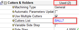
In the Multiple Cutters Selection dialog, select the cutters to be included in the procedure and click OK
 .
.The total number of cutters defined for the current procedure is displayed. The defined cutter is still BALL7—When other cutters have been defined, this can be changed.
Changing defined cutter in multiple cutters procedure
Select the currently defined cutter. A dropdown menu showing all the defined cutters is displayed.
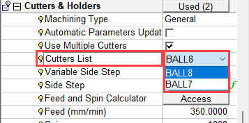
Select the required cutter. The cutter-specific parameter values are also changed.