|
|
Turning Operations: Setup B Operation
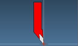
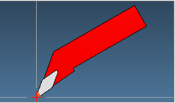
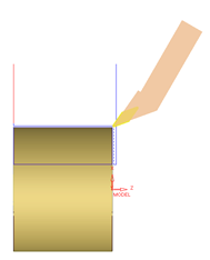
When setting up a turning cutter, it is required to touch the face and diameter of the part, with the tool. On head machines with certain shapes of holders, it is impossible to touch either the face or the diameter with the head axis at the zero position. Therefore, it is required to rotate the tool before setup. This is referred to as Setup B.
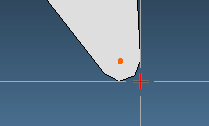
In the turning cutter dialog, the TT (Tool Tip) point is presented as a red cross.
When choosing a different Setup B orientation, the reference TT point changes, and therefore the output coordinates will change.
|
|
|
|
|
|
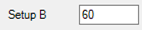
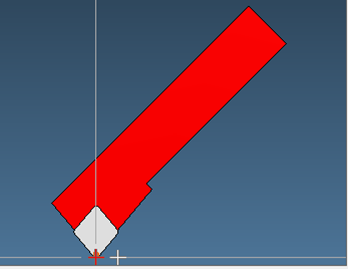
Note: In some cases, the user can select a different point as reference. In the two images below, you can see a red cross and a white cross – both can be used as a reference TT point. The one selected is the one in red.
|
|
|
|
TT point is in the middle of the insert |
TT point is on the right side of the insert |
The setup B angle is stored in the parameter LT_SETUP_B_ANG in the TOOL CHANGE block.
Examples
Case 1
The tool is set up straight and the orientation of the tool in the procedure is also straight.
The output is exactly on the face and on the diameter of the cylinder (X 50, Z 0).
|
(----------> Setup B 0 Rotate 90) G1 X18.8 F0.254 (Linear) Z0 (Linear) X50. (Linear) Z-81.2 (Linear) X52. (Linear) |
|
Case 2
The tool is set up straight and the orientation of the tool in the procedure is at 60 degrees.
The output is shifted by the vector X 0.761, Z -0.439.
|
(----------> Setup B 0 Rotate 60) G1 X19.561 F0.254 (Linear) Z-0.439 (Linear) X50.761 (Linear) Z-81.639 (Linear) X52.761 (Linear) |
|
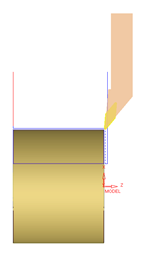
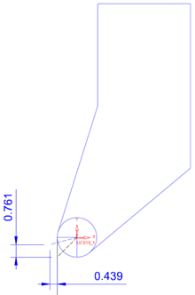
The following image shows how this vector is calculated:
|
The tool is setup as straight so the TT point is at the corner. Inside the procedure, the tool is rotated to be at 60 degrees, so the vector from the tool center to the reference TT point is rotated with the tool (by 30 degrees). The difference in X and Z are shown in the picture (the vector X 0.761, Z -0.439). These are the shifts in the coordinates seen in the above G-Code. |
|
Case 3
The tool is set up at 60 degrees and the orientation of the tool in the procedure is at 60 degrees.
Again, the output is exactly on the face and on the diameter of the cylinder (X 50, Z 0).
(----------> Setup B 60 Rotate 60
G1 X18.8 F0.254 (Linear)
Z0 (Linear)
X50. (Linear)
Z-81.2 (Linear)
X52. (Linear)
Case 4
The tool is set up at 60 degrees and the orientation of the tool in the procedure is at 90 degrees.
The output is shifted by the mirrored vector, i.e. (X -0.439, Z 0.761).
(----------> Setup B 60 Rotate 90
G1 X18.361 F0.254 (Linear)
Z0.761 (Linear)
X49.561 (Linear)
Z-80.439 (Linear)
|