Automatic Coordinate Table 
Access: Open this function from one of the following locations:
-
Click the
 button in the toolbar.
 -
Select Symbols > Automatic Symbols > Automatic Coordinate Table from the menu bar.
Automatically display a coordinate table listing all the coordinate labels in a selected view. These coordinate labels must first be created using the PMI Coordinate Label function in the Modeling environment.
You can select which columns appear in the Coordinate Table and also the font and character size that will be used. The font and character size are determined in the Drafting Font Style Preferences and the Drafting Character Style Preferences respectively. The column display is determined in the Automatic Coordinate Table dialog - see below.
Also see Editing a Coordinate Table.
Automatically display the coordinate table listing the coordinate labels
- InvokeInvoke the Automatic Coordinate Table function.
The Automatic Coordinate Table dialog is displayed:
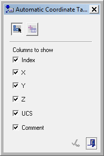
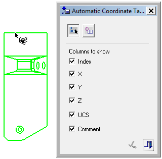
- Pick the view of the part containing the coordinate labels. Note that the
 button is active (pressed) in the Automatic Coordinate Table dialog.
For this example, the coordinate labels shown herethe coordinate labels shown here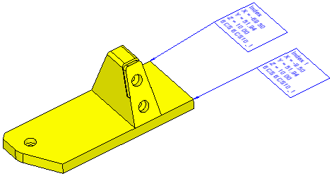 were created in the PMI Coordinate Label function and a view of the part was created.
- Pick the location to display the coordinate table. Note that the
 button is now active in the Automatic Coordinate Table dialog.
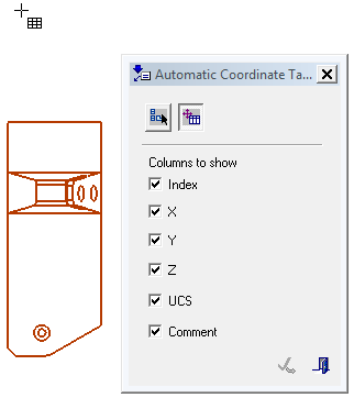
The position of the cursor indicates the location of the bottom left corner of the coordinate table.
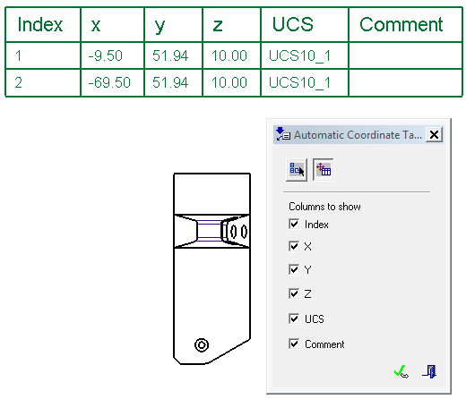
Choose which columns are displayed in the coordinate table by selecting/unselecting the appropriate checkboxes. By default, all the checkboxes are selected and the created table includes all the columns. Note that when a checkbox in unselected, it does not change the created table - the table still includes all the columns, however, the unselected column is not displayed in the table.
If the selected view did not contain any coordinate labels, an appropriate message is displayed when trying to position the table.
