BOM (Bill of Materials) 
![]()
![]()
Access: Open this function from one of the following locations:
-
Click
in the toolbar. -
Select Assembly > Main Tools > BOM from the menu bar.
-
Select BOM from the Mold Design Guide Toolbar.
Create a Bill of Materials (BoM) for an assembly. A BoM is a list of components in the assembly.
The BOM file contains all the data on the components that make up the complete Assembly.
Note: The BOM function is also available in the Drafting application for creating a Bill of Materials table for the drafting sheet. The BOM Table Editor dialog for an Assembly (described below) differs slightly from the dialog in the Drafting application. See the BOM Notes.
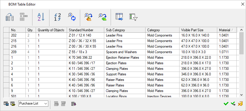
BOM Table Editor
Use the BOM Table Editor to perform operations on the BOM. These operations are similar to those available for the BOM Table Editor in the Drafting application.
See also:
- BOM Table Editor
- BOM Table Editing Operations - Assembly
- BOM Report - Assembly
- Dynamic Editing - Drag and Drop Operations
BOM Configuration File
A configuration file determines which attributes
appear in the BOM file.
The BOM_Template.csv file is the
BOM Configuration File; a resource
file which is used to define the relevant attributes to be displayed in
the Automatic BOM created from an Assembly. Usage instructions and column
descriptions are included in the CSV file.
...\ProgramData\Cimatron\Cimatron\2026.0\Data\Resource
English resource files are stored in the English sub-folder under Resource.
-
Creating reports
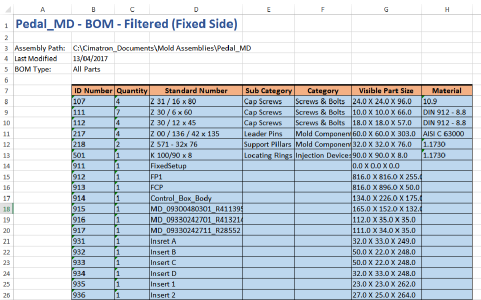
BOM reports can be created for a specific portion of the Assembly, such as a Sub-Assembly or folder or a selected group of components or visible parts, with or without catalog parts.
ExampleExampleThe example image below shows an Excel report of a BOM of the Fixed Side sub-assembly:
-
Marking components that require machining
Assembly components can be marked as those that require machining. The Requires Machining attribute is defined in the Cimatron Explorer Preview and Properties > Advanced tab. -
Assigning ID numbers
When assigning ID Numbers, components can be assigned new ID numbers or the ID numbers of deleted parts. A Preference option blocks the reuse of ID numbers of deleted items. In this case, the Recreate ID numbers command ignores these ID numbers. -
Filtering components for BOM report
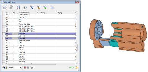
When exporting a BOM to a file, the Filtering option controls which components are shown in the BOM report.
ExampleExampleThe image below shows all components hidden except for those selected on the BOM:
-
Using the Standard Number attribute
Attribute modifications that are done to a part using the Properties Pane of the Cimatron Explorer will be updated automatically within the BOM when loading the Drafting file.
The Standard Number attribute is an exception since this attribute affects the BOM topology. (The number of rows in a Purchase List may change due to a change in this attribute.) Therefore, if the Standard Number attribute is changed through the Cimatron Explorer, the Assembly file should be opened first to update the BOM in the drawing.
It is highly recommended that the Standard Number attribute be modified (as well as other BOM-related attributes) via the BOM in the Assembly file. -
Quantity of objects
The Quantity of Objects column is available via the Column Chooser and displays the amount of objects in each part (not including cutting objects).
For Assemblies created prior to Cimatron 14, use the Copy ID Numbers & Quantities to All Parts option. This will save all parts when the Assembly is saved, and the Quantity of Objects will be updated.
The Quantity of Objects parameter also appears in the Cimatron Explorer > Preview and Properties > Advanced tab. -
Symbolic text
A relevant symbolic text is also available – %%PART_QUANTITY_OF_OBJECTS -
Single Unit in BOM attribute
If an Assembly has the Single Unit in BOM attribute turned ON, the following occurs:
- Any Assembly that participates as a Sub-Assembly in a second Assembly will appear as a single row in the BOM for that second Assembly.
- Components that belong to this Sub-Assembly will not be shown in the BOM.
- Instances of any part that participates in such a Sub-Assembly that also appears elsewhere in that Assembly will not be included when calculating quantity.
- The numbers are assigned normally by the Short Type attribute (from the Cimatron Explorer). An Assembly that does not have a Short Type will be considered as unassigned.
- If a single unit Assembly is opened separately (as a main Assembly), its BOM looks like a normal BOM.
-
The Copy ID numbers to all Sub-Assemblies function propagates the ID numbers in the main Assembly BOM down to the relevant parts of the Sub-Assembly BOM, ensuring that the Sub-Assembly BOM's ID numbers are identical to those in the main Assembly BOM. When enabled, this function automatically assigns ID numbers and quantities to any new parts and propagates these changes to the lower Sub-Assemblies. In the case of a single unit Assembly, its components will receive numbers only if their brothers have numbers. This feature remains active until you switch it off (Click the
 icon again). When the feature is inactive, ID numbers or quantities for any new parts are not updated in the Sub-Assemblies.
Note: Deactivating this function after it has been made switched on does NOT remove existing Part/Assembly file attributes (ID numbers and quantities).
The Copy ID numbers & quantities to all parts propagates the ID numbers in the main Assembly BOM down to the relevant parts of the Sub-Assembly BOM, ensuring that the Sub-Assembly BOM's ID numbers are identical to those in the main Assembly BOM.
When active, this function automatically assigns ID numbers and quantities to any new parts and propagates these changes to the lower Sub-Assemblies. In the case of a single unit Assembly, its components will receive numbers only if their siblings have numbers.
This feature remains active until you manually turn it off (click the
icon to deselect it). When deselected, ID numbers or quantities for any new parts are not updated in the Sub-Assemblies.Note: Deactivating this function after it has been made switched on does NOT remove existing Part/Assembly file attributes (ID numbers and quantities).
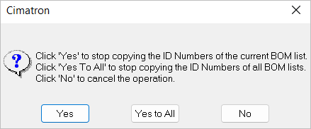
This dialog is displayed when you turn on the function.
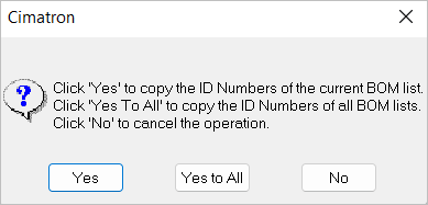
Yes
Copy the ID numbers of the current BOM list.
Yes to All
Copy the ID numbers of all BOM lists. The main Assembly ID numbers are copied to all Sub-Assembly lists: All parts, purchase list, and first level.
No
Cancel the operation.
When deactivating this function, this dialog is displayed.
Example: The BOM table of the main Assembly
Click the
icon—the confirmation dialog is displayed. Click Yes.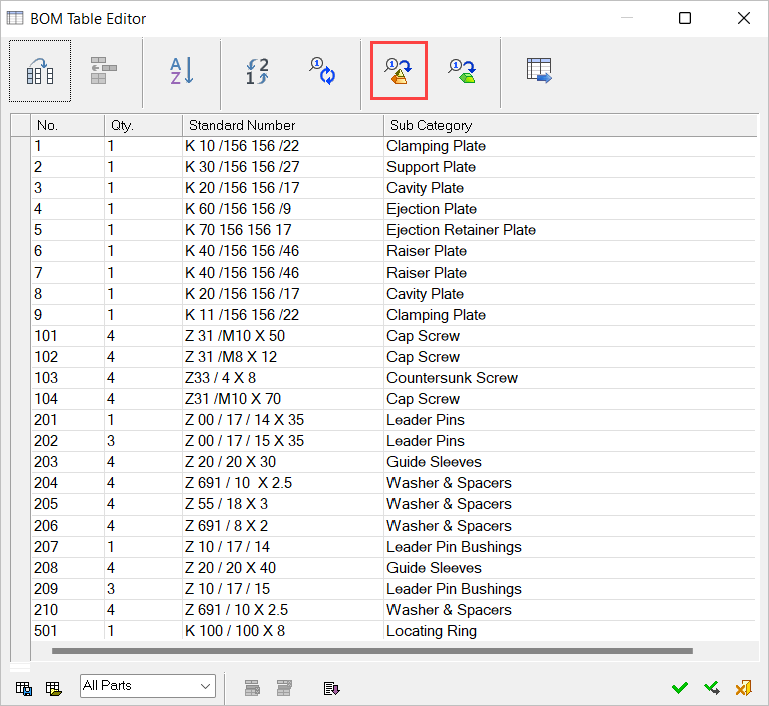
The BOM table of the Movable Side of the Assembly before copying ID numbers to all Sub-Assemblies.
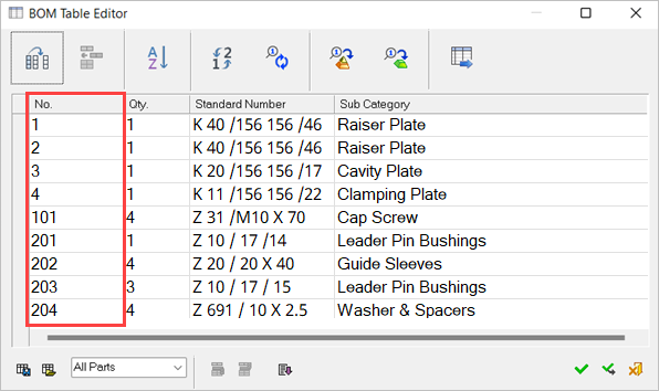
The BOM table of the Movable Side of the Assembly after copying ID numbers to all Sub-Assemblies. The ID numbers of the Sub-Assembly BOM are now the same as those of the main Assembly BOM. In this case, gaps may appear in the ID numbering.
