5X Applications  > Swarf by Contours
SWARF (Side Wall Axial Relief Feed) machining, or also called 'flank milling', is a 5-axis simultaneous milling process. It will be used for machining fluid parts for turbo-engines or aeronautical parts like integral elements.
To display additional parameters, click the relevant tab in the dialog image below.
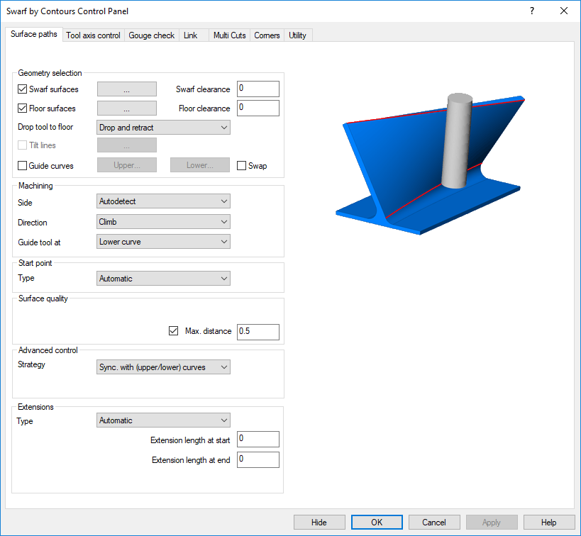
Tabs
Animations below may be shown automatically or by clicking the movie prompt image (like the demonstration image shown below):

Swarf by Contours
SWARF (Side Wall Axial Relief Feed) machining, or also called 'flank milling', is a 5-axis simultaneous milling process. It will be used for machining fluid parts for turbo-engines or aeronautical parts like integral elements.
The goal is to produce the target surface with only one cut, using the whole flute length of the tool.
The motivations are;
- better surface finish quality (without hand finish)
- shorter finish cycle time
- full access of machining areas through simultaneous 5-axis vector orientation
- constant cutting conditions (increased material removal, constant (low) cutting force)
The swarf machining will be used to produce the target surface with only one cut, using the whole flute length of the tool. Input geometry here is always an upper and lower curve. Different tilt cycles will be used to control the tool axis orientation.
This animation shows a typical application.
Gouges and rest material
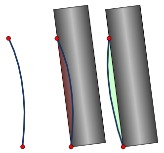
The swarf machining will align the tool always between 2 points on the upper and lower curve. The tool flank is a straight geometry while the actual surface is a free form surface and can be curved in any direction
The right picture describes the situation. The red points are the 2 curves, the blue line is the surface, viewed form the side as profile. In case the surface has a convex shape, the tool will gouge the surface. In case the surface has a concave shape the machining will leave rest material.
What does this mean?
It means that with swarf cutting you won't be able to create the real target surface, unless the surface between the 2 curves is 100% flat.
Solutions
The example is over-subscribed. Usually the error is not that big and can be tolerated by the user due to the fact that swarf cutting provides other advantages.
An automatic tilting cycle is available to minimize the error
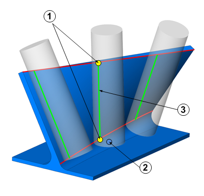
Contact Point, Tool Location, Tool Orientation
With swarf machining the tool will be aligned between 2 points (1) on 2 curves (red), an upper and a lower curve.
- Contact point - the point where the tool touches the 2 curves.
- Cutter Location Point - the point that is represented by the coordinates of the machine program.
- I, J, K Tool Orientation - values that represent the orientation of the tool axis.
Tools
Supported:
-
end mill
-
sphere mill
-
bullnose mill
-
taper mill
-
convex tip mill
-
dove mill
Not Supported:
-
lollipop mill
-
slot mill
-
barrel mill
-
drill tool
-
chamfer mill
Units
-
The calculation can be based on metric system or imperial system.
-
Metric means that all the values used in this calculation have 1 millimeter as unit.
-
Inch means that all the values used in this calculation have 1 inch as unit
-
When 'relative' values or angles in the settings are used, they are meant to be relative from the present tool path point or to the moving direction of the tool.