Check gouge between positions
This switch is set true to activate the collision checking between tool path positions. The 5-axis sweep move from one position to the next position is used to check for collisions with drive and check surfaces. To get proper tool paths and to avoid gouges, always check this option.
-
Especially on flat surface tool path points will be generated only at the edge of a surface. Between this points no tool path points will be generated so the gouge checking wouldn't realize a gouge.
-
When you set a distance, this function might not be necessary.
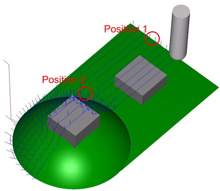
Option deactivated
No gouge check between positions
- On the flat part no tool path points lie between the edges. The tool will gouge with the grey check surface.
- On the round part many tool path points exists. Here the gouge checking would work even with deactivated function.
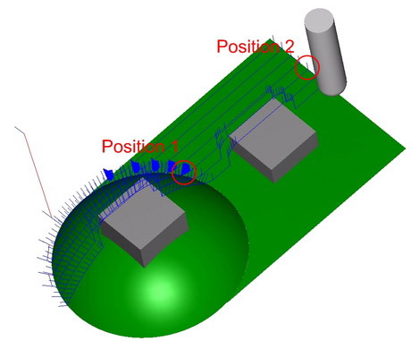
Option activated
- On the flat part no tool path points lie between the edges. With the activated option the system finds the the grey check surface and avoids the gouge.
- On the round part many tool path points exists. Here the gouge checking works even with deactivated function.
Extend tool to infinity
This option switches the extension of tool geometry to infinity on and off. If this flag is set to true, then the tool, arbor, and holder passed by the user will be considered with the given length for collision checking purposes. For several reasons, it might be desirable to extend the last used portion of the tool with a cylinder to infinity. This will help the collision checking system to detect all collisions happening.
A good example for this case is related to using guide surfaces (e.g. like a thin cylinder) and then retracting with the tool to the actual part geometry defined as check surfaces. If the total tool length (including holder and arbor) is not long enough, the collision checking system can find a collision free location for the tool between the thin cylinder and real part geometry. In this case, making the tool longer resolves the problem. With this flag turned on, it is not necessary to change the tool length manually to a larger value.
Check link motions for collisions
This parameter switches the check of link moves for collision during tool path generation on and off.
The idea is to take activated tool parts and check faces from all gouge check sets. The collision avoidance follows a simple fall back system which is different for the different link types:
For the First Entry and Last Exit thinks are different from the interlinks.
If the user selects 'Approach from feed distance', and if it fails, the algorithm increases the feed distance until a limit value. If that fails the algorithm is making the tool path for First entry and/or Last Exit using the user values. In this case the resulted tool path will be in collision and the user will notice and will be forced to change some settings.
If the user selects 'Approach from rapid distance', and if it fails, the algorithm increases the retract distance until a limit value. If that fails the algorithm changes the retract distance to user inputted value and increase the distance to clearance area. If this fails also, the algorithm is making the tool path for First entry and/or Last Exit using the user values. In this case the resulted tool path will be in collision and the user will notice and will be forced to change some settings.
If we select 'Approach from clearance area', and if it fails, the algorithm increases the retract distance until a limit value. If that fails the algorithm changes the retract distance to user inputted value and increase the distance to clearance area. the algorithm is making the tool path for First entry and/or Last Exit using the user values. In this case the resulted tool path will be in collision and the user will notice and will be forced to change some settings.
For interlinks
-
The algorithm is constructing the user options. If one fails the algorithm tries the next one.
-
The order is like in user interface:
-
Direct
-
Fallow Surfaces
-
Blend Spline
-
Retract to Feed Distance
-
Retract to Rapid Distance
-
Retract to Clearance Area
-
For example:
-
If the option 2 is selected and fails, the option 3 is tried next. If this one fails too, the next one (option 4) is tried, and so on.
-
If the option 5 fails the algorithm is changing the air move safety distance and tries again. If this change has no good effect, the next option is tried (option 6).
-
At the option 6 the algorithm is using the approach from First Entry or Last Exit.
-
If all this fails the algorithm make a tool path using the option "6. Retract to Clearance Area". In this case the resulted tool path will be in collision and the user will notice and will be forced to change some settings.
Check link motions against containment
This parameter makes sure that direct, blend spline or follow surface links stay within the containments and in case the tool path has to cross cut the containments the links be replaced with the clearance area linking.
The containments can be
-
The active containment
This can be the 2D containment or/and Silhouette containment -
Other curves
-
A user defined curve picked by the user.
-
This animation shows a linking without collision check
-

Option activated
This animation shows the same example with containment collision check.

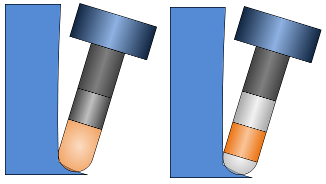
Check tool tip
This switch can be used for collision check strategy 'tilt tool away'. It deactivates gouge checking for the radius portion of the flute (in case a ball mill or bull mill is used).
The left picture shows that the tool tilts away from the wall to avoid a collision with the holder. But this forces the tool tip to gouge with the floor. Now the collision check would then try to tilt away the tool from the floor as well, but as you can see this is not possible. The contact point of the tool stays the same, in this case the tool would simply rotate around the contact point of tool and surface. The collision can't be solved. The result is a tool path which is not collision free.
In the image you see that the flute is not checked for collisions. Now the tool path is not collision free either, but the calculation will not fail because in this case it does find a solution. The remaining collisions can be removed with an additional gouge check strategy.