Picking Aiming Surfaces
Access: Open this function from the following location:
-
Part surface selection mode:
Either press the button in the Work Mode Dialog (if you are in Wizard Mode), or display the Geometry parameters in the parameter tables.
The Geometry Table is displayed:
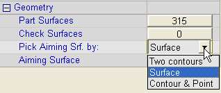
Click the dropdown menu next to Pick Aiming Srf. by:, and select the option to define the aiming surface. You are then prompted to pick the required geometry.
See Selecting / Unselecting Geometry.
See the cursor symbols in Cimatron when picking geometry.
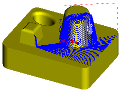
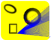
Aiming surfaces define the area where the milling is to be performed.
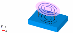
The following aiming surface options are available:
Note: In a Local Operations - Aiming Surface procedure, the aiming surface can only be picked manually!
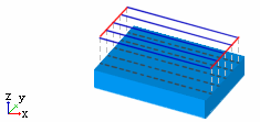
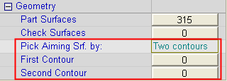
2 Contours
Pick two contours. Make sure the direction arrows of both contours are pointing the same way, otherwise a twisted surface may be created. The area between the contours is milled.
Warning: When defining the dummy surface, do not use any geometric options (planes, UCS, Sketcher) as this may cause database problems.
|
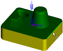
Pick First Contour |
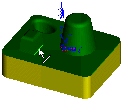
Pick Second Contour |
|
|
|
|
|
|
|
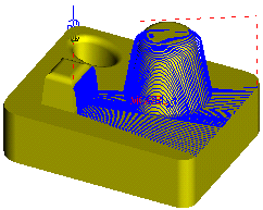
Result: ISO View |
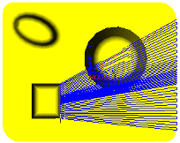
Result: Top View |
|
|
|
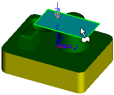
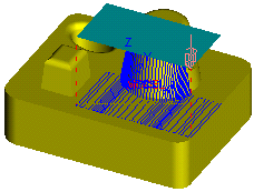
Surface
Pick an aiming surface to define the milling area on the target surface.


|
Pick Aiming Surface |
Result |
|
|
|
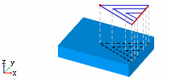
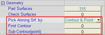
Contour & Point
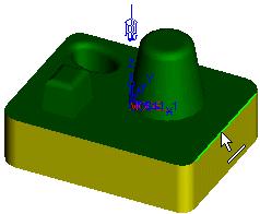
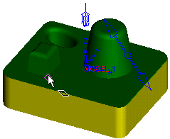
Pick a contour and a point. The area between the contour and point is milled.
Warning: When defining the dummy surface, do not use any geometric options (planes, UCS, Sketcher) as this may cause database problems.
|
Contour |
Point |
|
|
|
|
Result: ISO View |
Result: Top View |
|
|
|
