Contour Manager (NC): Contour Creation - Chamfer Detect
![]()
![]()
Access: Open this function from one of the following locations:
-
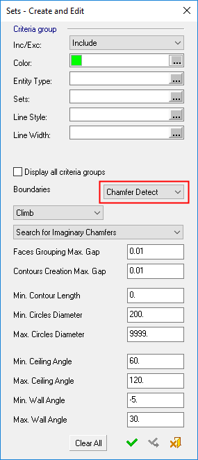
Select the By Criteria option in the Contour Manager. Then select the dropdown option Chamfer Detect from the Sets - Create and Edit dialog.
-
Select the Chamfer Detect option in the Contour Manager.
|
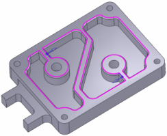
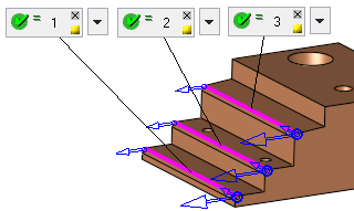
Automatically detect sharp edges as candidates for chamfering ("Imaginary" chamfers) as well as "Designed" chamfers, based on parameter settings. The detected geometry is then automatically used as input for the chamfering toolpath. The Chamfer Detect option is displayed for the procedures: Chamfer Open Contour and Chamfer Closed Contour. |
The image shows chamfers automatically detected for machining.
|
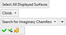
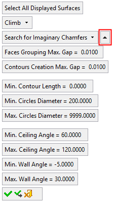
Additional contour definition parameters are displayed in the graphics window for greater control over the contour creation.
These parameters can either be set from the By Criteria dialog or from the parameters displayed from the Chamfer Detect option.
|
Contour Manager > By Criteria: |
Contour Manager > Multi Contours Selection: |
||
|
Criteria dialog for selecting contours with Boundaries = Chamfer Detect: |
Auto Chamfer Detect, |
Auto Chamfer Detect, |
|
|
|
|
|
|
Parameters:
|
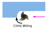
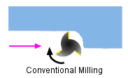
Climb |
Select the cutting mode toggle option Climb / Conventional:
Notes: The Climb/Conventional parameter sets the parameter of each created contour as follows:
|
||||||||
|
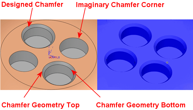
Search for Imaginary Chamfers |
Set the chamfer search mode from the dropdown list. This parameter obtains its initial value from the Contour Represents parameter in the Tool Trajectory branch of the parameter table for the Chamfer Open Contour and Chamfer Closed Contour procedures. However, the value in the graphics window can be changed via the dropdown list. For additional information see the Contour Represents parameter.
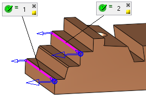
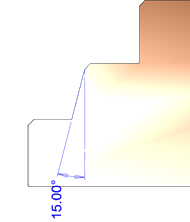
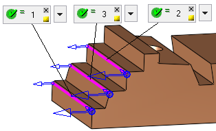
The image below left shows chamfers designed into the part and also chamfers that are to be milled using the Imaginary Chamfer Corner option. Examples of the Top and Bottom Chamfer Geometry contours are also shown. The image below right shows the chamfered results.
|
||||||||
|
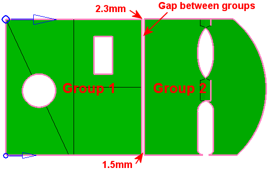
Faces Grouping Max. Gap |
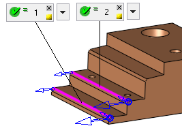
Create Contour geometry based on this Max. Gap value. This maximum gap value is used to analyze the groups of selected faces and create the required geometry. This parameter is used to group faces according to the defined Max. Gap value (the selected faces are grouped considering the gaps between them). In the example below, there are two groups of faces separated by a gap
of 1.5 to 2.3 millimeters. In this example, the Faces
Grouping Max. Gap parameter = 1mm, hence the two groups.
If the Faces
Grouping Max. Gap value is changed to 2.5 (greater than both gap
values), the boundary segments that were before on both sides of the gap
no longer exist. All faces are now grouped in one group.
See the note below regarding this parameter.
|
||||||||
|
Contours Creation Max. Gap |
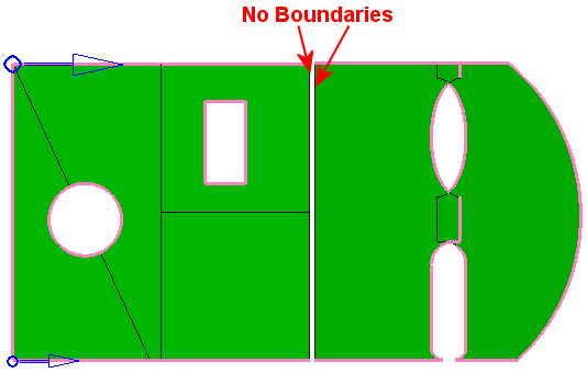
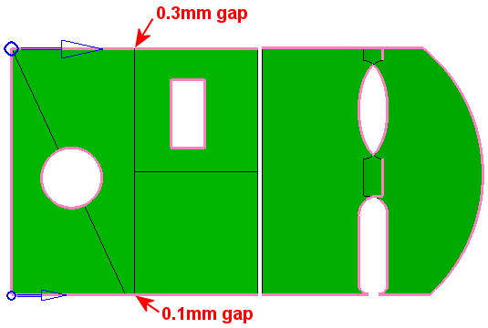
Create Contour geometry based on this Max. Gap value. This maximum gap value is used to analyze the edges of the selected faces and create the required geometry. This parameter is used to concatenate the edges to one or more segments, according to the defined Max. Gap value. In the example below, there are two gaps along the contours
(0.1 and 0.3 millimeters wide). In this example, the Contours
Creation Max. Gap parameter = 0.02mm, which is smaller than any
of the gaps.
If the Contours Creation Max. Gap parameter is gradually changed to be greater than any one of the existing gaps (0.2, 0.4, 2 and 2.5), you will notice that the gaps in the contours close one after the other. The contour changes immediately when the changes are done, as the Preview mode is automatic. See the note below regarding this parameter.
|
||||||||
|
Min. Contour Length |
Contours smaller than the defined length will not be created. |
||||||||
|
Min./Max. Circles Diameter |
The diameter range values beyond which holes are not taken into account when creating contours. |
||||||||
|
Min./Max. Ceiling Angle |
The angle range values beyond which ceilings are not taken into account when the system searches for geometry from which to create contours. If Min./Max. Ceiling Angle = 90°, then the system only detects ceilings that are parallel to the XY plane. Result when searching for Chamfer Geometry Top, Min./Max. Ceiling Angle = 90°:
If Min. = 60° and Max. Ceiling Angle = 120°, then the system detects ceilings within that angle range from the parallel to the XY plane. Result when searching for Chamfer Geometry Top, Min. = 60°, Max. Ceiling Angle = 120°:
See Angle Limits, below. |
||||||||
|
Min./Max. Wall Angle |
The angle range values beyond which walls are not taken into account when the system searches for geometry from which to create contours. If Min./Max. Wall Angle = 0°, then the system only detects walls that are normal to the XY plane. Result when searching for Chamfer Geometry Top, Min./Max. Wall Angle = 0°:
If Min. = 0° and Max. Wall Angle = 20°, then the system detects tapered walls up to 20° from the normal to the XY plane. Result when searching for Chamfer Geometry Top, Min. = 0°, Max. Wall Angle = 20°:
See Angle Limits, below. |
||||||||
|
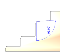
Min./Max. Chamfer Angle |
The angle range values beyond which chamfers are not taken into account when the system searches for geometry from which to create contours. If Min. = 44 and Max. Chamfer Angle = 46, then the system detects designed chamfers within the range of 44° to 46°. See Angle Limits, below. |
||||||||
Notes:
-
The creation of some contours may be prevented if the Faces Grouping Max. Gap value is greater than the Contours Creation Max. Gap value. In this case, an appropriate warning message is displayed.
-
To hide or show entities that are already participating in NC contours, right-click in the graphics area and select the displayed popup option; Show entities already participating in NC contours or Hide entities already participating in NC contours. See Contour Popup Operations for additional information.
Angle Limits
The angle limits parameters and values that are displayed, depend on the Search for... parameter value.
Imaginary Chamfer:
|
Parameter |
Default |
Min. |
Max. |
|
Min. Ceiling Angle |
60 |
45 |
120 |
|
Max. Ceiling Angle |
120 |
60 |
150 |
|
Min. Wall Angle |
-5 |
-45 |
45 |
|
Max. Wall Angle |
30 |
0 |
60 |
Geometry Top:
|
Parameter |
Default |
Min. |
Max. |
|
Min. Ceiling Angle |
60 |
45 |
120 |
|
Max. Ceiling Angle |
120 |
60 |
150 |
|
Min. Chamfer Angle |
Draft-1 |
10 |
84 |
|
Max. Chamfer Angle |
Draft+1 |
11 |
85 |
Geometry Bottom:
|
Parameter |
Default |
Min. |
Max. |
|
Min. Chamfer Angle |
Draft-1 |
10 |
84 |
|
Max. Chamfer Angle |
Draft+1 |
11 |
85 |
|
Min. Wall Angle |
-5 |
-45 |
45 |
|
Max. Wall Angle |
45 |
0 |
60 |
In all cases, Min. Angle ≤ Max. Angle.
Draft is the conic angle of the cutter (for Conic cutters or Counter Sink cutters) or 45° otherwise.
There are three possible types of faces that can meet on a chamfer: Ceiling, Draft and Wall. The selected Search for parameter defines which two face types out of the three are used.
Approval Buttons
|
|
OK: Accept the changes, perform the operation, and close the current dialog/task. |
|
|
Apply: Accept the changes, perform the operation, and keep the current dialog/task open. |
|
|
Cancel: Cancel all changes and close the dialog/task without saving the settings. |
When either OK ![]() or Apply
or Apply ![]() is clicked, the system creates 2D NC contours, parallel to the procedure’s XY plane; duplicated contours are not created. Edges that are not parallel to the XY main plane of the procedure's UCS are disregarded.
is clicked, the system creates 2D NC contours, parallel to the procedure’s XY plane; duplicated contours are not created. Edges that are not parallel to the XY main plane of the procedure's UCS are disregarded.