Contour Manager (NC) > Multi Contours Selection
![]()
![]()
Access: Open this function from the following location:
Boundary/Contour selection mode:
Either press the button in the Work
Mode Dialog (if you are in Wizard
Mode), or display the Geometry
parameters in the parameter
tables.
button in the Work
Mode Dialog (if you are in Wizard
Mode), or display the Geometry
parameters in the parameter
tables.
The Geometry Table is displayed:
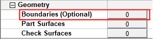
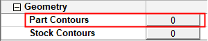
Depending on the current operation, the Boundaries or Contours option is displayed. Press the adjacent button to display the Contour Manager; you are ready to start selecting contours.
See Selecting / Unselecting Geometry.
See the cursor symbols in Cimatron when picking geometry.
Create multiple NC contours from multiple selected curves or the boundaries of selected faces. This option enables the creation of multiple contours from the following entities:
The creation of multiple contours from outer and inner boundaries of groups of faces. The created contours are closed contours. This functionality is available to all relevant procedures.
The creation of multiple contours from groups of vertical faces. The created contours are projected contours. This functionality is available to all procedures that accept composite curve contours.
Additional contour definition parameters are displayed in the graphics window for greater control over the contour creation.
|
Select All Displayed Surfaces |
Create multiple contours from all the curves that are displayed. |
||||||||||
|
Faces Boundaries, Outer Only |
Create multiple contours based on one of the following dropdown list of options:
A group of faces may have one or more faces. |
||||||||||
|
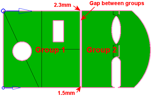
Faces Grouping Max. Gap |
Create Contour geometry based on this Max. Gap value. This maximum gap value is used to analyze the groups of selected faces and create the required geometry. This parameter is used to group faces according to the defined Max. Gap value (the selected faces are grouped considering the gaps between them). In the example below, there are two groups of faces separated by a gap
of 1.5 to 2.3 millimeters. In this example, the Faces
Grouping Max. Gap parameter = 1mm, hence the two groups.
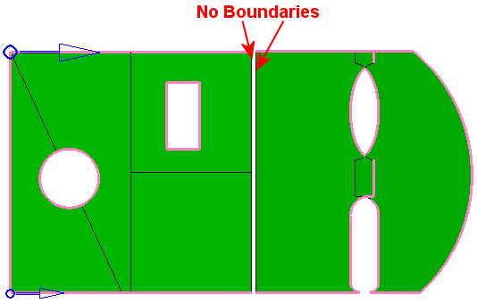
If the Faces
Grouping Max. Gap value is changed to 2.5 (greater than both gap
values), the boundary segments that were before on both sides of the gap
no longer exist. All faces are now grouped in one group.
See the note below regarding this parameter.
|
||||||||||
|
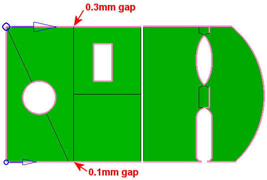
Contours Creation Max. Gap |
Create Contour geometry based on this Max. Gap value. This maximum gap value is used to analyze the edges of the selected faces and create the required geometry. This parameter is used to concatenate the edges to one or more segments, according to the defined Max. Gap value. In the example below, there are two gaps along the contours
(0.1 and 0.3 millimeters wide). In this example, the Contours
Creation Max. Gap parameter = 0.02mm, which is smaller than any
of the gaps.
If the Contours Creation Max. Gap parameter is gradually changed to be greater than any one of the existing gaps (0.2, 0.4, 2 and 2.5), you will notice that the gaps in the contours close one after the other. The contour changes immediately when the changes are done, as the Preview mode is automatic. See the note below regarding this parameter.
|
Notes:
-
The creation of some contours may be prevented if the Faces Grouping Max. Gap value is greater than the Contours Creation Max. Gap value. In this case, an appropriate warning message is displayed.
-
To hide or show entities that are already participating in NC contours, right-click in the graphics area and select the displayed popup option; Show entities already participating in NC contours or Hide entities already participating in NC contours. See Contour Popup Operations for additional information.
To explain this option, the following example is used:

All the displayed curves: Press the Select All Displayed Surfaces option:
In this case, all the displayed curves are selected by the system, as shown below:

When you press OK to finish the contour selection, the contour labels are displayed and you can see how many contours were created (in this case 2):
Click on the labels to highlight the individual curves that make-up each contour.