Machine Docking Pane
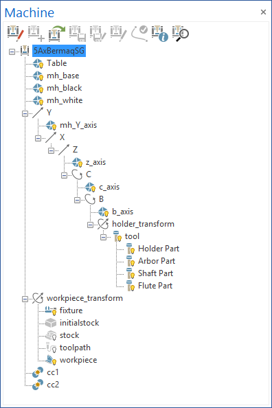
The Machine docking pane shows the machine kinematics. Use the docking pane to edit the kinematics and control the visibility of the machine geometries during the simulation.
There are two ways to work with the Machine docking pane:
|
|
Simulation Mode
In Simulation Mode the editing functions are greyed out and unavailable. Simulation Mode offers the following functionality:
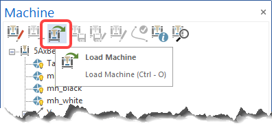 |
Load Machine: Load a machine definition file (*.xml). |
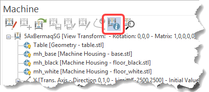 |
Show Information: Display the most important information for each machine object (this is also available in Edit Machine Mode). |
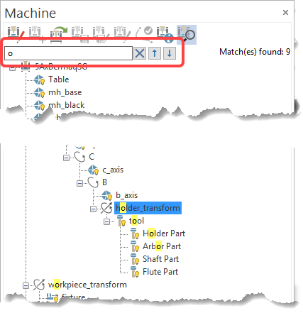 |
Machine Kinematic Search: Find objects in the machine kinematics that contain the entered search characters.
|
 |
|
Machine Edit Mode
Machine Edit Mode enables you to edit the machine elements and kinematics.
-
Edit Machine: Click the Edit Machine button to enter Machine Edit Mode. In this Mode, all the editing buttons in the Machine docking pane are available.
Machine Edit Mode offers the following commands:
-
New Machine: create a new machine
-
Save: Save the edited machine. If the machine is new and no *.xml file was created, you are prompted to specify a location and file name for the machine.
-
Save Machine As...: Save the edited machine under a different name or in a different folder.
-
Edit Machine in external editor: Open the machine .xml files in your default application or, if a path has been set, open the files via the application pointed to by the path.
-
Reload machine definition: Reload the OpenGL viewport with the current changes directly in Machine Edit Mode.
The machine .xml file name must be identical with the folder name in which the xml is stored.
Machine Simulator saves all relevant files in the same folder (including the machine geometries (*.stl) and transparency (*.bmp) files).
Machine Edit Mode - Context Menu
Right-mouse-click on an element to open a context menu with commands applicable to that element. The Context Menu contains items that can be added to the element. The available items depend on the type of element selected. Here is a description of all the items that can be added:
-
Add Transl. Axis: Add a translation axis to the machine kinematics:
-
X, Y, Z Axis: Add a translation axis with an already defined direction: X, Y and Z
-
User Defined: Add a translation axis with a user-defined direction.
-
Settings: For a translation axis, you can define these settings:
-
ID: Define the ID of an axis.
-
Show slider: Show/hide the axis in the Axis control window.
-
Direction (X, Y, Z): Define the direction of the axis.
-
Limits: Define the minimum and maximum limits of the axis. Axis movement is limited according to the limits you enter here.
-
Min: The minimum limit of an axis.
-
Max: The maximum limit of an axis.
-
Value Type: Select the axis value type (Continuous, Discrete Stepped, Discrete List).
-
Step Value: This field is available only when the Discrete Stepped Value Type is selected. Enter the value of the step that is used to internally calculate the accepted values.
-
List of Values (semicolon separated): This field is available only when the Discrete List Value Type is selected. Enter each value that the respective axis can take, separated by a semicolon ";"
-
Initial Value: Define the initial value for an axis. During machine loading, the axis appears in the position given by the initial value.
-
-
-
-
For the Discrete Stepped and Discrete List Values Type, the Machine Simulation automatically adjusts the Initial Value to the closest valid value after the user inputs it,
For the Discrete Stepped Value Type, the Machine Simulation considers the Limits Min value as the starting value for creating the interval. For example, if the Limits Min value is 4 and the Step Value is 5, the accepted values will be: 4, 9, 14, 19, ... until the Limits Max value.
For the Discrete List Value Type, the Machine Simulation automatically sets the Min and Max limits according to the defined List of Values. For example, if the List of Values consists of 2, 4, 8, 10 then the Min limit will be 2 and the Max limit will be 10.
-
Add Rot. Axis: Add a rotation axis to the machine kinematics:
-
A, B, C Axis: Add a rotation axis with a pre-defined rotation direction: A, B, and C.
-
User Defined: Add a rotation axis with a user-defined rotation direction.
-
Settings: Define specific settings for any rotation axis:
-
ID: Define the ID of an axis.
-
Show slider: Show/hide the axis in the Axis control window.
-
Direction (X, Y, Z): Define the direction of the axis.
-
Rot. Base Point (X, Y, Z): Define the rotation base point of the rotation axis.
-
Limits: Define the minimum and maximum limits of the axis. Axis movement is limited according to the limits you enter here.
-
Min: The minimum limit of an axis.
-
Max: The maximum limit of an axis.
-
Value Type: Select the axis value type (Continuous, Discrete Stepped, Discrete List).
-
Step Value: This field is available only when the Discrete Stepped Value Type is selected. Enter the value of the step that is used to internally calculate the accepted values.
-
List of Values (semicolon separated): This field is available only when the Discrete List Value Type is selected. Enter each value that the respective axis can take, separated by a semicolon ";"
-
Initial Value: Define the initial value for an axis. During machine loading, the axis appears in the position given by the initial value.
-
-
-
-
For the Discrete Stepped and Discrete List Values Type, the Machine Simulation automatically adjusts the Initial Value to the closest valid value after the user inputs it,
For the Discrete Stepped Value Type, the Machine Simulation considers the Limits Min value as the starting value for creating the interval. For example, if the Limits Min value is 4 and the Step Value is 5, the accepted values will be: 4, 9, 14, 19, ... until the Limits Max value.
For the Discrete List Value Type, the Machine Simulation automatically sets the Min and Max limits according to the defined List of Values. For example, if the List of Values consists of 2, 4, 8, 10 then the Min limit will be 2 and the Max limit will be 10.
-
Add Coord. Transform: Select a coordinate transform element for the machine kinematics:
-
Workpiece Transform: Add a workpiece transform object to the machine kinematics.
-
Holder Transform: Add a holder transform object to the machine kinematics.
-
User Defined: Add a user-defined transform object to the machine kinematics.
-
Settings: Define the settings for a coordinate transform object:
-
ID: Define the ID of the transform object.
-
Matrix values from Machine Definition: Define the transform matrix of an object:
-
Rotation (around X, Y, Z degrees): Define the rotations around the X, Y and Z axes for a transform object.
-
Shift (along X, Y, Z): Define the translation values along the X, Y and Z directions for a transform object.
-
Advanced Rotation and Shift Matrix: This represents the transformation matrix of an object (it is automatically calculated from the Rotation and Shift values).
-
-
Apply on-screen values from program (Yes/No): in Edit Machine Mode, this option enables you to distinguish between the matrix provided in the XML file and the one that is applied on the screen at that moment.
-
Relative Program Matrix (Yes/No): This setting lets you separately view the original matrix from the machine definition XML file and another matrix that represents the difference that is used to show the object on the screen, as it is seen at that moment.
-
Matrix values from Program: These settings let you see the transform matrix from the program:
-
Rotation (around X, Y, Z degrees): View the rotations defined via the program.
-
Shift (along X, Y, Z): View the translations defined via the program.
-
Advanced Rotation and Shift Matrix: This represents the transformation matrix that is automatically calculated from the Rotation and Shift values.
-
-
-
-
-
Add Dynamic Element: Add a dynamic element to the machine kinematics:
-
Workpiece: Define a workpiece (target part) element.
-
Fixture: Define a stock fixture or chuck and jaws (from a clamp system). Usually, the jaws are defined under the translation or rotation axis and the chuck is above these, but under the spindle rotation axis and the Workpiece Spindle Revolving Group.
-
Stock: Define a stock fixture or chuck and jaws (from a clamp system). Usually, the jaws are defined under the translation or rotation axis and the chuck is above these, but under the spindle rotation axis.
-
Initial Stock: Define the Initial Stock element.
-
Toolpath: Define the toolpath line.
-
Tool: Define the tool element made of Flute, Shaft, Arbor and Holder.
-
Workpiece Spindle Revolving Group: This is defined under the spindle rotation axis and usually contains the Fixture and Geometry objects for the clamp system (chuck and jaws) and the Workpiece Set.
-
Tool Spindle Revolving Group: This is defined last in the kinematic branch and contains geometry objects that rotate with the tool, and the Tool Set.
-
Workpiece Set: Add a workpiece set to the machine kinematics (workpiece_transform, containing workpiece, fixture, stock, initial stock and toolpath).
-
Tool Set: Add a tool set (holder transform, containing the tool with all its parts : holder, arbor, shaft and flute) to the machine kinematics.
The Workpiece, Fixture, Stock, Initial Stock and Toolpath objects should all be located under a Workpiece Set. Only Fixture objects can appear outside a Workpiece Set to define clamp systems.
-
-
Add Geometry: Add one or multiple geometries to the machine kinematics.
-
Settings: You can define the following settings for a geometry:
-
ID: The ID of a geometry. By default, the ID of the geometry takes the name of the .stl file that will be used for that geometry, but afterwards it can be changed.
-
Color: Select the geometry color
-
Transparency (0-100%): Set the transparency level for the selected geometry. Enter a value between 0 (opaque) and 100 (hidden).
-
Reflectivity (0-100%): Set the reflectivity level for the selected geometry. Enter a value between 0 and 100.
-
Geometry: Select the .stl file that will be shown on the screen for the selected geometry.
-
Reflect Map: Introduce a .bmp file that will be used as a reflection map for the selected geometry.
-
-
-
Add Tail Stock: Add a tail stock object to the machine kinematics.
-
Settings: Define specific settings for the tail stock:
-
ID: Define the ID of the tail stock. By default, the ID is "tailstock".
-
Color: Select the tail stock color.
-
Transparency (0-100%): Set the transparency level for the selected tail stock. Enter a value between 0 (opaque) and 100 (hidden).
-
Reflectivity (0-100%): Set the reflectivity level for the selected tail stock. Enter a value between 0 and 100.
-
Reflect Map: Introduce a .bmp file that will be used as a reflection map for the selected tailstock.
-
-
-
Add Collision Check: The collision checking elements are defined by setting two groups. Each component from one group is checked against all components from the other group. The Proximity Alert functionality also relies on the groups made here. Once the option is selected, it opens a sub-menu with two elements:
-
Tool-Workpiece/Stock: By default, this collision check element contains the workpiece, stock and fixture for one group, and the tools for the other. You can add/remove other elements in both groups. Only elements not in the machine magazine can be added using this option. If there is not at least one element available for each group, the button becomes inactive.
-
User Defined: By default, this collision check element is empty and allows you to add/remove elements as needed.
-
Settings: Define the settings for the cc element:
-
Blue left panel: The first group of elements are used for collision checking against the second group.
-
+ icon: Add machine elements to the first group. Select Done when finished.
-
- icon: Remove machine elements from the first group.
-
-
Red right panel: The second group of elements that are used for collision checking against the first group.
-
+ icon: Add machine elements to the second group. Select Done when finished.
-
- icon: Remove machine elements from the second group.
-
-
-
-
Add Magazine: Add a magazine with one or multiple mount entities to the machine kinematics.
-
Add Wire Heads: Add wire heads (upper and lower heads) to the machine kinematics to define a Wire Machine.
-
Add Upper Head: Add the upper head represented by one geometry,
-
Add Lower Head: Add the lower head represented by one geometry.
-
Settings:
-
For the Lower Head, a normal geometry object is added (see Settings->Add Geometry)
-
For the Upper Head:
-
ID: Define the ID of the upper head.
-
Geometry: Select the geometry that will be used as upper head.
-
Associated Lower Head: Select the lower head that is associated with the upper one.
-
Color: Select the upper head geometry color.
-
Transparency (0-100%): Set the transparency level for the upper head geometry. Enter a value between 0 (opaque) and 100 (hidden).
-
Reflectivity (0-100%): Set the reflectivity level for the upper head geometry. Enter a value between 0 and 100.
-
Reflect Map: Introduce a bmp file that will be used as a reflection map for the upper head geometry.
-
-
-
-
Add Mount Adapter: Add a mount adapter object to the machine kinematics. This is used to mount heads from the magazine.
-
Head Adapter: Add a head adapter to the machine kinematics.
-
Table Adapter: Add a table adapter to the machine kinematics.
-
User Defined: Add a user-defined mount adapter to the machine kinematics.
-
Settings: (same as "Add Coord. Transform" above).
-
-
Add Mount Entity: Add one or multiple mount entities to the machine kinematics. These can be mounted in the mount adapters during the simulation.
-
Settings:
-
ID: Enter the ID of the mount_entity. By default, the ID is "mount_entity".
-
-
-
Make as Machine Housing: Right-mouse-click on a geometry to open a sub-menu that enables you to select any normal geometry as the machine housing geometry. The selected geometry is automatically renamed (for instance, "ID = geometry" becomes "ID = mh_geometry"). The visibility of this geometry is controlled via the Machine Housing button on the Visibility toolbar.
-
Remove as Machine Housing: Right-mouse-click on a machine housing geometry to open a sub-menu, that enables you to select any machine housing geometry as the normal geometry. The selected geometry is automatically renamed (for instance, "ID = mh_geometry" becomes "ID = geometry").