Simulation Area
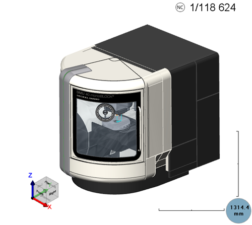
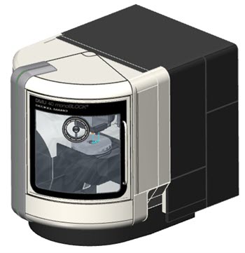
The Simulation Area is usually the largest area of the screen. This is where users can view the simulation process.
The following elements are visible in the Simulation Area:
Machine Model and other geometries
The main element in the Simulation Area is the machine model itself. In some cases only the workpiece (target part) or stock (in process material) or tool are visible.
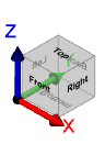
Coordinate System and Rotation Cube
The coordinate cross shows the orientation and direction of the X, Y and Z axes.
The Machine Simulator uses the right-handed coordinate system. The right-handed coordinate system (or positive) is where the xy-plane is horizontal and the z-axis points upwards (and the x- and y-axis form a positively oriented two-dimensional coordinate system in the xy-plane when observed from above the xy-plane). Positive rotation is counterclockwise about the axis of rotation (or using the right-hand rule for vectors, where the vector is the axis).
The rotation cube enables you to set the view accordingly:
- by clicking on different faces to change the view to Top, Front, Right, Left, Back, or Bottom
- by clicking on the cube's edge intersections to change the view to intermediary 3D orientations (similar to the Isometric view).
Machine Coordinate System
The coordinate cross shows the orientation and direction of the X, Y and Z axes as corresponding to the machine definition.
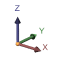
The coordinate system can be right- or left-handed coordinate system. The detection works automatically in most cases where the machine can be recognized. But, there are cases were complex machines are defined with axis names that are not the common X, Y or Z, and then the coordinate system may be the default one (equivalent with the "Coordinate System").
Ruler
The Ruler can be used for measuring and evaluating different distances.
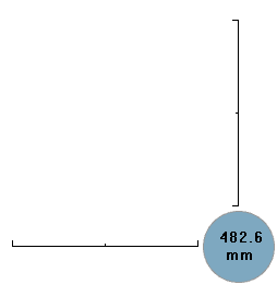
The displayed value shows the length of each of the two perpendicular bars, and is updated by each movement. So, anything on the simulation screen with the length of this bar has the dimensions of the displayed value. The middle marking on each of the bars represents half the displayed value.
Machine Center Point
The Machine Center Point indicates the zero point from the CAD system in relation to which all geometries were drawn.

It also represent the point that is used to define the axis rotation center points or workpiece and tool mounting points. It has the following elements:
- it is colored in black and white.
- the dotted points represent the positive direction for the X, Y and Z coordinate system. Red for X, green for Y and blue for Z.
If both Machine Center Point and Work Coordinate Point are displayed at the same point in space, the point will be colored black and blue.
Work Coordinate Point
The Work Coordinate Point indicates the zero point of the toolpath (and also, in some cases, the workpiece and stock zero point used in the CAM system when the toolpath was calculated).

It has the following elements:
- it is colored blue and white.
- the dotted points represent the positive direction for the X, Y and Z coordinate system. Red for X, green for Y and blue for Z.
If both Work Coordinate Point and Machine Center Point are displayed at the same point in space, the point will be colored black and blue.
Additional Info based on Simulation Mode
The information displayed in this panel is based on the Simulation Mode:
-
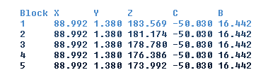
NC-based Mode: the current block / the total number of simulation blocks.
Block numbers are unique numbers generated for the entire simulation (all operations), starting with 1, which count all the moves provided to the Machine Simulator.
- Time-based Mode: the current running time / total running time (format is HH:MM:SS.S - HH-hours; MM-minutes; SS.S-seconds)
- Length-based Mode: the traveled distance up to the current point / the total distance for the entire simulation.
Simulation Area Embedded Move List
This Move List can be activated and positioned only inside the CAD/CAM application.
The move list offers limited functionality compared to the Move List docking pane.
Displaying this Move List embedded in the Simulation Area can sometimes slow down the simulation.
Simulation Area Watermark
The Simulation Area can also contain a Watermark message centered in the bottom side of it.

The message itself can be customised according to your preferences and so can the colour itself.
Simulation Area Context Menu
The Simulation Area context menulets you quickly choose from a collection of functionalities related to Zoom, Rotation, Tool/Machine Repositioning, Visibilities, Views, Viewports and Capturing the Simulation Area.
Open the context menu by clicking on areas of the UI listed below:
-
Simulation Area to access the functionalities related to Zoom, Rotation, Visibilities, Views, Viewports, and Capturing the Simulation Area.
-
Zoom Window: Allows you to select 2 points on the Simulation Area. The selected points are used for zooming-in.
Right-mouse click to select the points. Use the Esc key or right-mouse click outside of the Simulation Area to cancel the selection. -
Pick-Point Dynamic Rotation: This type of rotation is based on Euler rotation defined around a selected point.
-
Other Visibilities: Use this option to select visibilities like Show / Opaque / Transparent / Hide for the following elements:
-
Toolpath
-
Tool
-
Fixture
-
Workpiece
-
Stock
-
Initial Stock
-
Machine Housing
-
-
Views: Use this option to select a view:
-
Fit to Screen
-
Isometric
-
Other views:
-
Top
-
Bottom
-
Front
-
Back
-
Right
-
Left
-
-
-
Viewports: Use this option to select one of the Viewports or to reset them:
-
Maximize
-
4 Views
-
3 Views
-
2 Rows
-
2 Columns
-
Reset Views Layout
-
Reset Views Content
-
-
Previous View: Use this option to select a previous view recorded by the Machine Simulator:
-
View 1
-
View 2
-
...
-
-
Capture: This allows to quickly capture a picture or a video of the Simulation/Graphics Area.
- Capture Graphics Area: capture a picture.
- Start Capture Video: start capturing a video.
- Capture Options...: open the Options dialog at Capture.
-
- A geometry: when you click on a geometry to open the context menu, the menu will contain an option to set the respective geometry to Show / Opaque / Transparent / Hide.
- A tool: when you click on a tool to open the context menu, the menu gives you the option to configure the respective tool to Show / Opaque / Transparent / Hide. Also, for selected tool you can select the visibility of individual tool parts via the sub-menus for Holder, Arbor, Shaft and Flute.
- Toolpath: when you click on a tool to open the context menu, you get options to Show / Hide the toolpath as well as to jump to the selected toolpath position.
Main Navigation Keys and Mouse commands
You need to navigate in the Simulation Window to observe the model and simulation process. Here are a few basic actions:
- Rotation: Spin the geometry on the screen.
- Using the mouse: The geometry rotates around the mouse pointer. Click and drag to rotate the geometry.
- Using the keyboard: The geometry will rotate around the center of the machine. Hold the up-down-left-right arrow keys (default).
- Zoom: Use the Zoom command to make the geometry appear closer or farther away on the screen.
- Using the mouse: Use the mouse-wheel to zoom in or zoom out.
- Using the keyboard: Press the Z (zoom in) or Shift-Z (zoom out) keys (default).
- Pan: Use the Pan (2D shift) command to traverse the geometry across the screen.
- Using the mouse: Right-click and drag (default).
- Using the keyboard: Press and hold the Ctrl + Arrow keys (default).
Jog in Simulation Area
There are multiple possibilities to jog in the simulation area, and all involve clicking on the tool geometry. The advantage of this functionality is that Machine Simulator will solve the kinematic automatically. This is very useful in the case of robots or other complex machines with many axes.
- Jog on any plane orthogonal to the tool axis direction: this can be achieved by pressing CTRL+SHIFT+left mouse click (default). In this case, the tool can be moved either along its axis direction or in any orthogonal plane formed by its direction.
- Jog along tool axis direction: this can be achieved by pressing CTRL+SHIFT+right mouse click (default). This, in comparison with the previous jog, restricts the tool only to its direction.
- Bring the tool tip position to a mouse position: this can be achieved by pressing SHIFT+double left mouse click (default) on an object from the simulation window where you want the tool tip to be positioned.
All these actions will not induce any simulation or material removal.