No Core Cut (Pocket) Start Point
Create a pocketing process.
Note: A start point must be defined before creating a pocketing process. This is done during the part construction.
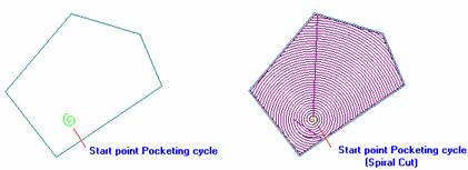
You can see how the start point affects the toolpath.
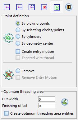 |
Point Definition
-
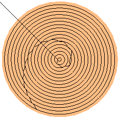
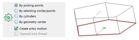
By picking points: Select any point within the contour by using any point selection methods available in Cimatron (such as free point, center point, and so on). The contour must be closed. The start point will be indicated by the spiral iconspiral icon
 .
. -
By selecting circles/points: Use the center point or the selected point. For single and multiple contours, you can select one or more points or circles and Cimatron will detect the points inside each contour.
-
By cylinders: Use the center point or the cylinder section at the proper height. For single and multiple contours, you can select cylinders and Cimatron will detect the points inside each contour.
-
By geometry center: Select all the parts you want to automatically create start points. Cimatron will calculate the geometric center of each element and create a start point there.
-
Create entry motion: Mark this checkbox to create a point - projection entry motion, with the start point as approximation point, whenever possible.
-
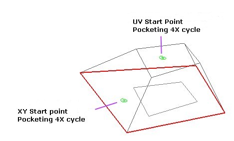
Tapered wire thread: This option is avilable there are different XY and UV contours. The type of selection of start point will be the same for both contours, and the selection order will be XY - UV.
-
Remove: Delete an existing start point. Select Remove and click the point to delete. The point will automatically be removed (it is not necessary to delete the start point to redefine it).
-
Remove entry motion: This option is available when Remove is selected. Use this option to delete both the start point for pocketing and the previously created entry motion.
Optimum threading area
The location of the start point for pocketing is a very important factor for the toolpath calculation, particularly in 4x Pocketing. This optimum location not is always easy to find.
Defining approximate (but realistic) values for Cut width and Finishing offset will display the optimum areas to locate the threading point.
-
Mark the Create optimum threading area entities checkboxCreate optimum threading area entities checkbox
 to have these areas be generated as CAD geometry.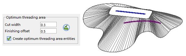
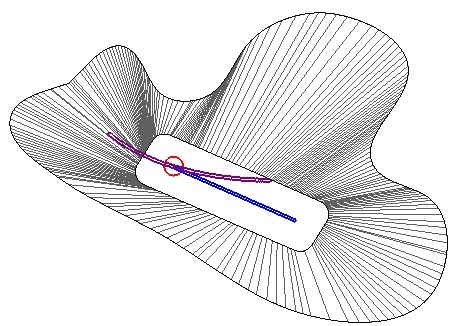
In this example, the (virtual) intersection between the XY area and the UV area will be the best optimum area for the threading point.