Gun Drill Dialog

Access: In the Machine
Parameters table, press the Access
button adjacent to the Gun Drill
Parameters option.
The Gun Drill Parameters option
is displayed in the Machine Parameters
table if (in the Tool Trajectory table) the Drill
Type = Gun Drill.
Automated
Drill Tool Trajectory parameters availability
In the Automated
Drill procedure, once a drilling
sequence has been created, and if the Cutter
Sequence Data table has at least one entry, the Automated
Drill - Tool Trajectory parameters become available. Some of these
parameters are also displayed in the Cutter
Sequence Data table. Depending on the Drill
Type you have selected (in the Tool
Trajectory table), some parameters may not be available or other
parameters may be displayed.
Gun drilling is a delicate operation requiring specific settings in order to protect the tool from breaking when encountering differing geometry conditions while drilling.
Cimatron enables full control over the complete drilling sequence, enabling you to define the drill's spindle speed, spindle direction, feed rates and distances at various points, and for all gun drilling scenarios. The Gun Drill dialog provides you with an enhanced visual understanding of the gun drilling process, showing you the different drilling scenarios and their respective parameters.
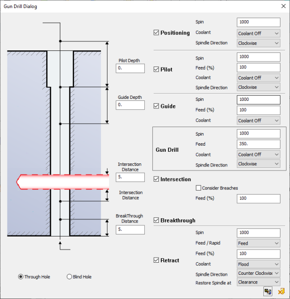
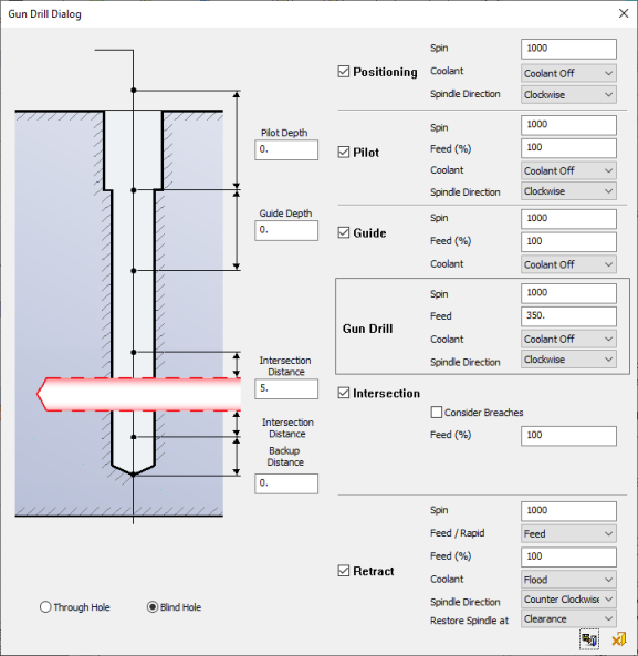
The Gun Drill dialog changes slightly depending upon the type of hole - Through or Blind. Both dialogs are shown below to show the visual differences. A full view of each dialog and all the parameter descriptions are detailed below.
The Gun Drill dialog is displayed. The examples below show the dialogs for a Through Hole and for a Blind Hole.
|
|
|
|
Gun Drill Dialog - Through Hole
|
Gun Drill Dialog - Blind Hole
|
Dialog Buttons
Different parameter values may be defined for each segment in the Gun Drill dialog. The following parameters appear for both Through and Blind Holes, unless specifically stated:
Note: In addition to these parameters, set the Dwell for Spin Change in the Machine Parameters Table.
|
Positioning
|
Select the Positioning checkbox to display and set the following parameters for the Positioning Point above the hole:
|
Spin
|
Set the Positioning Spin value.
Range of values = 1 - 999999. Default = 1000.
|
|
Coolant
|
Set the required Coolant type(s) from the displayed User Defined Coolant dialog.
The coolant types and pressure values displayed
in the dialog are defined in the NC
Preferences (for each coolant type that is checked ON in the preference
and given a coolant name).
|
|
Spindle Direction
|
Set the Positioning Spindle Direction type from the following dropdown list of values:
Clockwise (default)
Counter Clockwise
Off
|
If the Positioning checkbox is unselected, the Spin and Coolant in the Positioning area are as defined in the following existing segment of the dialog: Pilot, Guide or Gun Drill).
|
|
Pilot
|
Select the Pilot checkbox to display and set the following parameters for the Pilot area above the hole.
Before entering the material, Gun Drills first go through a pre-drilled 'Pilot' that stabilizes the tool and may supply coolant and aid with chip removal.
|
Pilot Depth
|
Set the Pilot Depth. The Pilot depth is considered to be a section of the hole that has already been pre-drilled, i.e. there is no material. Any intersection or breach which is found above the pilot depth is ignored.
If Pilot Depth is not used, any intersections or breaches above the reference depth are ignored.
Range of absolute distance values = 0 - 9999. Default = 0.
|
|
Spin
|
Set the Pilot Spin value.
Range of values = 1 - 999999. Default = 1000.
|
|
Feed (%)
|
Set the Pilot Feed %.
Range of values = 0.001 - 999999. Default = 100.
|
|
Coolant
|
Set the required Coolant type(s) from the displayed User Defined Coolant dialog.
The coolant types and pressure values displayed
in the dialog are defined in the NC
Preferences (for each coolant type that is checked ON in the preference
and given a coolant name).
|
|
Spindle Direction
|
Set the Pilot Spindle Direction type from the following dropdown list of values:
Clockwise (default)
Counter Clockwise
Off
|
If the Pilot checkbox is unselected, the Pilot Depth = 0.
|
|
Guide
|
Select the Guide checkbox to display and set the following parameters for the Guide area of the hole:
|
Guide Depth
|
Set the Guide Depth.
Range of absolute distance values = 0 - 9999. Default = 0.
|
|
Spin
|
Set the Guide Spin value.
Range of values = 1 - 999999. Default = 1000.
|
|
Feed (%)
|
Set the Guide Feed %.
Range of values = 0.001 - 999999. Default = 100.
|
|
Coolant
|
Set the required Coolant type(s) from the displayed User Defined Coolant dialog.
The coolant types and pressure values displayed
in the dialog are defined in the NC
Preferences (for each coolant type that is checked ON in the preference
and given a coolant name).
|
If the Guide checkbox is unselected, the Guide Depth = 0.
|
|
Gun Drill
|
Set the following Gun Drill parameters:
|
Spin
|
Set the Gun Drill Spin value.
Range of values = 1 - 999999. Default = 1000.
|
|
Feed
|
Set the Gun Drill Feed.
Default = 350.
|
|
Coolant
|
Set the required Coolant type(s) from the displayed User Defined Coolant dialog.
The coolant types and pressure values displayed
in the dialog are defined in the NC
Preferences (for each coolant type that is checked ON in the preference
and given a coolant name).
|
|
Spindle Direction
|
Set the Gun Drill Spindle Direction type from the following dropdown list of values:
Clockwise (default)
Counter Clockwise
Off
|
|
|
Intersection
|
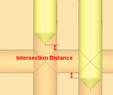
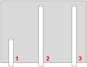
Select the Intersection checkbox to display and set the following parameters when the drilling intersects another hole.
Slowing the drill when it arrives at an intersection of other cooling channels or pockets helps prevent unnecessary strain on the tool. Cimatron automatically knows if the intersecting holes have been drilled and slows down only when they have, leading to improved machining times and a longer tool life. The system enables you to control the drill 'slowing down' distance.
Example:Example:
|
The gun drill does
not need to slow down if starting with channels 1,
2 and 3.
|
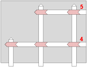
The gun drill slows
down for channels 4 and 5 at the red intersections,
as channels 1, 2 and 3 are already drilled.
|
|
|
|
|
Intersection Distance
|
Set the Intersection Distance. The Intersection Distance is the distance before and after intersection to reduce feed. Before the intersection, it is the distance between the tool tip and the start of the intersection. After the intersection, it is the distance between the end of the intersection and the full diameter of the tool.
Example:Example:
Range of values = 0 - 9999. Default = 5.
|
|
Consider Breaches
|
Gun Drill may require reducing the feed rate at intersections between holes. Breaches at the top of the holes are considered as intersections and therefore the feed may be reduced at the breaches.
When this checkbox is ON  , the feed is reduced at breaches. , the feed is reduced at breaches.
Default = OFF 
|
|
Feed (%)
|
Set the Pilot Feed %.
Range of values = 0.001 - 999999. Default = 100.
|
If the Intersection checkbox is unselect, then ignore intersections.
|
|
Breakthrough
|
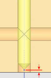
This parameter is only displayed for Through Holes. Select the Breakthrough checkbox to display and set the following parameters when the drilling breaks through the part to the other side:
|
Breakthrough Distance
|
Set the Breakthrough Distance. The Breakthrough distance is the distance before final breakthrough of a 'Through' hole at which the feed rate is reduced. It is the distance between the bottom of the hole and the tool tip.
Example:Example:
Range of values = 0 - 9999. Default = 5.
|
If the Breakthrough checkbox is unselected, then ignore breakthroughs.
|
|
Backup Distance
|
This parameter is only displayed for Blind Holes. Set the Backup Distance.
Range of values = 0 - 9999. Default = 0.
If the Backup Distance > 0, then retract this distance from the bottom of the hole at Drill Feed before changing the spin and spindle direction.
|
|
Retract
|
Select the Retract checkbox to display and set the following parameters for the Retract area of the hole:
|
Spin
|
Set the Retract Spin value.
Range of values = 1 - 999999. Default = 1000.
|
|
Feed/Rapid
|
Set the retract speed from the following dropdown list of values:
Feed (default)
Rapid
If Rapid is selected, the Feed (%) parameter (below) is unavailable.
|
|
Feed (%)
|
Set the Retract Feed %.
Range of values = 0.001 - 999999. Default = 100.
|
|
Coolant
|
Set the required Coolant type(s) from the displayed User Defined Coolant dialog.
The coolant types and pressure values displayed
in the dialog are defined in the NC
Preferences (for each coolant type that is checked ON in the preference
and given a coolant name).
|
|
Spindle Direction
|
Set the Retract Spindle Direction type from the following dropdown list of values:
Clockwise (default)
Counter Clockwise
Off
|
|
Restore Spindle at
|
If the Retract Spindle Direction ≠ Gun Drill Spindle Direction, this parameter sets the point at which the spindle resumes the spin direction set by the Gun Drill Spindle Direction.
The available options are from the following dropdown list of values:
Top of Hole
Clearance (default)
If the Retract Spindle Direction = Gun Drill Spindle Direction, this parameter is unavailable.
|
If the Retract checkbox is unselected, then retract at normal feed, spin and coolant.
|
Dialog Buttons:
|

|
Save and Close: Close the dialog and update the procedure parameter values with the last values displayed in the dialog.
|
|

|
Cancel: Close the dialog without updating the procedure parameter values. This also occurs by pressing the "X" of the dialog.
|