Tool Trajectory Parameters: Turning  > Contour
  - Contour Tab
Take a single turning pass along a shape, creating a smooth surface
finish.
Used for finishing operations.
The Tool Trajectory parameters for Turning > Contours are displayed in a dialog. The Contour tab is displayed below.
|
|
Contour Cut Options |
|||||
|
|
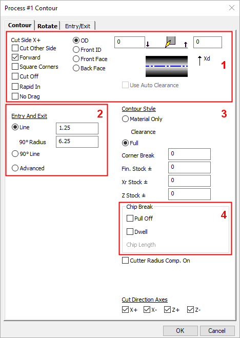
These checkboxes indicate the direction the tool will move along the designated cut shape. |
||||
|
Cut Side X+ |
Cut Side tells you which side (usually X+ or X-) will be cut. To flip
the positioning, select or deselect the Cut Other Side checkbox.
|
||||
|
Cut Other Side |
|||||
|
Forward |
This indicates the direction the tool will move along the designated cut shape. |
||||
|
Square Corners |
Determines the external corner moves for a cut shape. |
||||
|
Cut Off |
For use with cut off tools. |
||||
|
Rapid In |
Specify the move speed from the Entry Clearance Plane position to the start point of the toolpath. |
||||
|
No Drag |
Indicates how the contour will be cut. |
||||
|
Approach/Retract Type |
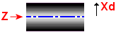
The Approach/Retract Type selection designates the axis along which the tool will approach and retract from the part. These are similar for all Turning procedures, with the exception of Lathe Drill. On most turning machines, X is radial and Z is axial, as shown below.
The OD (Outside
Diameter of the part) and Front ID (Front
Inside Diameter
of the part) approach type options specify that the tool approaches and
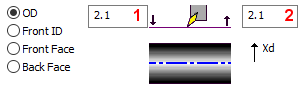
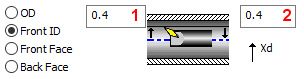
retracts radially along the X axis, on most turning machines. Once the Approach Type is selected, the corresponding Clearance diagram appears in the Process dialog. The boxes with the arrows next to them represent the Entry and Exit Clearance Positions that the tool may use when approaching and retracting from the part; both boxes are labeled with arrows going towards and away from the part, respectively. The Entry and Exit Clearance Positions are only required when Auto Clearance is turned OFF. Entry Clearance Diameter/Radius
specifies the location to which the tool will make a rapid move, before
it begins to feed radially to the operation's start point.
Exit Clearance Diameter/Radius
specifies the location to which the tool will make a rapid move, after
it has completed cutting at the operation's end point.
|
||||
|
OD |
The OD approach type option deploys the toolpath on the Outer Diameter of the part. For this option, the following Clearance Diagram is displayed:
|
||||
|
Front ID |
The Front ID approach type option deploys the toolpath on the Front Inner Diameter of the part. For this option, the following Clearance Diagram is displayed:
|
||||
|
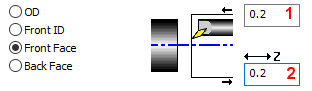
Front Face |
The Front Face approach type option deploys the toolpath onto the Front Face (Z+) of the part. For this option, the following Clearance Diagram is displayed:
|
||||
|
Back Face |
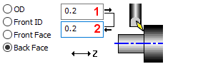
The Back Face approach type option deploys the toolpath onto the Back Face (Z-) of the part. For this option, the following Clearance Diagram is displayed:
|
||||
|
Auto Clearance |
Specify whether the clearance positions are to be calculated automatically
by the system or are fixed positions based on a user-defined part clearance
position. The Auto Clearance option performs several functions when it is turned on. It will calculate the part clearances in both Z and X that are used to position the tool between each operation. These positioning moves will be dynamically calculated for each operation. This means that as the stock conditions of the part change as material is removed, the clearance positions will adjust accordingly. When Auto Clearance is ON, the system will also take into account where the tool needs to be to begin the next operations' toolpath when calculating the positioning moves. Additionally, the Auto Clearance function may add entry and/or exit moves to the toolpath in order to safely maneuver around the part. The Auto Clearance function generates the most efficient positioning moves around a part. However, canned cycles cannot be used in conjunction with Auto Clearance. In order to use canned cycles, which are turned on in Process (Tool Trajectory) dialogs by selecting the Prefer Canned option, Fixed Clearance positions must be used. The Auto Clearance option requires the user to enter an offset amount from the part stock that the system uses to calculate the clearance positioning moves between operations. Because the stock conditions are constantly changing as material is removed from the part, in order to optimize the toolpaths, an offset amount is used for positioning rather than absolute positions. Fixed clearance, which is used when Auto Clearance is turned off, uses absolute positions. When this option is OFF,
fixed clearance positions are used by the system to calculate clearance
moves. In this case, you need to enter an overall part clearance in the
Clearance
& UCS Motion Parameters (in the Xr/Xd
and Z text boxes), as well as
Entry and Exit Clearance Positions in the Process dialogs for each operation.
When using canned cycles, fixed clearance positioning should be used. When the Auto Clearance option is turned OFF, fixed clearance positions are used by the system to calculate clearance moves. The user must enter an overall part clearance in the Clearance & UCS Motion Parameters, as well as Entry and Exit Clearance Positions in the Process dialogs for each operation. When using canned cycles, fixed clearance positioning should be used. The overall part clearance is entered in the Clearance & UCS parameters in the Xr/Xd and Z text boxes that become active when Auto Clearance is turned off. They designate the position the tool will rapid to and from during a tool change. This position will also be used when moving from one approach type to another between operations that use the same tool. The absolute positions specified in the Xr/Xd and Z text boxes are locations the tool can rapid to when moving around the part. One or both of these fixed positions are used whenever a tool is moving to the start point of the toolpath or exiting from the toolpath. Where the tool moves when approaching and retracting from the part depends on the Approach Type selected and the positions specified in the Clearance Diagrams in the Process dialog.
|
||||
|
|
|||||
Contour Entry and Exit |
|||||
|
|
The Entry and Exit options can create additional movements that will be added to the toolpath. |
||||
|
Line |
When this option is selected, a 90° arc of the specified radius value will be added to the toolpath. This arc will be tangent to the start feature at the start point. If a value is entered in the Line text box, a line of the specified length will be created tangent to the arc. Also, if this is selected and the radius value is zero, the line will not be perpendicular but instead will be parallel. |
||||
|
90° Line |
When this option is selected, a line of the specified length will be added to the cut shape. This line will be perpendicular to the start feature at the start point. |
||||
|
Advanced |
Selecting the Advanced option allows you to define custom Entry and Exit Moves using the Entry/Exit tab. |
||||
|
|
|||||
Contour Style |
|||||
|
|
The Contour Style selection affects the toolpaths created for the current operation. |
||||
|
Material Only |
When this option is ON, the system keeps track of material that has already been removed. Calculations are performed on the exact shape of material left from the initial stock shape and all prior machining operations. The toolpath will only feed over areas that have not yet been machined in previous operations, providing for "no air cutting." Because of this, the order of operations directly affects how the part will be cut. If the order of operations is changed or operations are added or removed, all operations should be recalculated in order to account for the change. |
||||
|
Clearance |
The Clearance value specifies an offset amount from the material that
the system uses to calculate where the tool can safely rapid during an
operation. If the tool is within the clearance amount, only feed moves
will be allowed. |
||||
|
Full |
The Full option gives you more control over toolpath creation. |
||||
|
Corner Break |
The Corner Break value specifies a radius that will be put on every outside sharp corner of the selected cut shape. A value of zero will not break the corner, but will keep the tool in contact with the part as it moves to the next feature. Corner Break is only available when Square Corners is not selected. |
||||
|
Fin. Stock ± |
The Finished Stock value specifies the minimum amount of material that will be left outside the part geometry (equally on all faces) after a toolpath is completed. The toolpath will be offset from the part geometry in Z and in Xd. This excess material is removed with the finish pass. |
||||
|
Xr Stock |
The Xr Stock value allows you to specify any additional stock amount for the X axis. The value entered here specifies the amount of material that will be left on the cut shape along the X axis only. |
||||
|
Z Stock |
The Z Stock value allows you to specify a stock amount for the Z axis. The Z Stock value specifies the amount of material that will be left on the cut shape along the Z axis only. |
||||
|
Cutter Radius Compensation On |
A checkbox that indicates whether Cutter Radius Compensation (CRC) is turned ON When this checkbox is ON Cimatron has a number of rules for when and where it will generate CRC markers. These rules have been chosen so as to be as safe as possible for the widest range of machines. This means that while a specific machine may be able to handle different CRC rules, Cimatron will not generate markers for all cases by default. CRC rules on arcs are the primary example of this. For new toolpaths, the system will do the following:
CRC will be activated on entry moves, before the entry arc. If there is no move before the entry arc, CRC will be activated on the arc. The system has a warning that will tell you when you are using CRC without a line move. In general, the system considers CRC activation on an arc to be an invalid case, because it does not accurately cut the arc. CRC will be activated on exit moves, after the exit arc. If there is no move after the exit arc, the CRC deactivation will be made on the Depth move. Again, the system will warn you when you do not have a line move. In general, the system considers CRC deactivation on an arc to be an invalid case, because it does not accurately cut the arc. Some Operations have the option of deferring CRC activation until later in the toolpath (roughing with a finish pass.) Rules 1 and 2 will be applied to the finish pass only.
For old Toolpaths, the system will only follow rules 1 and 2. No markers will be added for rapids imbedded in the toolpath. When exiting the Process dialog by clicking the OK button, the cutter compensation mode is displayed, dimmed, in the Enable Cutter Compensation field of the procedure's parameter table grid, under Machine Parameters. When this option is OFF, the following is displayed in the parameter table:
When this checkbox is ON
See Cutter Compensation for additional details. |
||||
|
Cut Direction Axes |
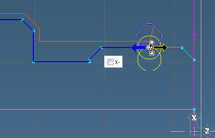
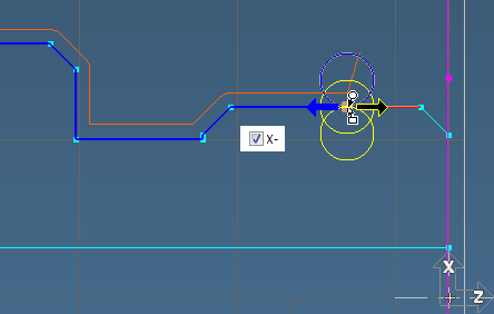
The Cut Direction Axes checkboxes allow you to limit motion along the cut axis, thereby regulating the axes and directions of the cut shape.
|
||||
|
|
|||||
Chip Break |
|||||
|
|
The Contour and Rough Turning procedures provide a Chip Break capability which give you the ability to break off chips according to set parameters. These parameters are useful when machining material that is soft or spongy, where chips can sometimes be quite long, interfering with the machining of the part. Note: A post change is required if your existing post does not support the output of Dwell in the toolpath. If you are unsure, contact your Provider or Reseller to verify or request a modification. |
||||
|
Pull Off |
When this checkbox is ON |
||||
|
Dwell |
When this checkbox is ON |
||||
|
Chip Length |
Specify the length of chip to tolerate before Pull Off and/or Dwell
occur. The length of chips that are removed will remain constant even
though the circumference of the stock diminishes (in an OD process). |
||||
|
|
|||||