Tool Trajectory Parameters: Turning  > Groove
  - Groove Cycle Tab
Create geometry-independent rectangular grooves.
Used for predefined groove cycles.
The Tool Trajectory parameters for Turning > Groove are displayed in a dialog. The Groove Cycle tab is displayed below.
|
|
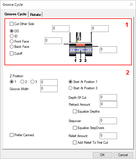
Groove Cut Options |
||||
|
|
These checkboxes indicate the direction the tool will move along the designated cut shape. |
|||
|
Cut Other Side |
Specify whether to use the non-primary side of the tool. For example, an X+ tool for the outer diameter (OD) might use the X- side to cut on the inner diameter (ID). |
|||
|
Approach/Retract Type |
The Approach/Retract Type selection designates the axis along which
the tool will approach and retract from the part. These are similar for
all Turning procedures,
with the exception of Lathe
Drill.
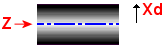
On most turning machines, X is radial and Z is axial, as shown below.
The OD (Outside
Diameter of the part) and Front ID (Front
Inside Diameter
of the part) approach type options specify that the tool approaches and
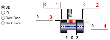
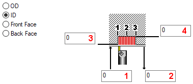
retracts radially along the X axis, on most turning machines. Once the Approach Type is selected, the corresponding Clearance diagram appears in the Process dialog. The boxes with the arrows next to them represent the Entry and Exit Clearance Positions that the tool may use when approaching and retracting from the part; both boxes are labeled with arrows going towards and away from the part, respectively. The Entry and Exit Clearance Positions are only required when Auto Clearance is turned OFF. Entry Clearance Diameter/Radius
specifies the location to which the tool will make a rapid move, before
it begins to feed radially to the operation's start point.
Exit Clearance Diameter/Radius
specifies the location to which the tool will make a rapid move, after
it has completed cutting at the operation's end point.
|
|||
|
OD |
The OD approach type option
deploys the toolpath on the Outer
Diameter of the part.
For this option, the following Clearance Diagram is displayed:
|
|||
|
ID |
For this option, the following Clearance Diagram is displayed:
|
|||
|
Front Face |
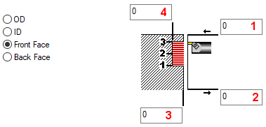
The Front Face approach type
option deploys the toolpath onto the Front
Face (Z+) of the part.
For this option, the following Clearance Diagram is displayed:
|
|||
|
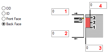
Back Face |
The Back Face approach type
option deploys the toolpath onto the Back
Face (Z-) of the part.
For this option, the following Clearance Diagram is displayed:
|
|||
|
Cutoff |
When this checkbox is ON  , the postprocessor considers this a cutoff process. , the postprocessor considers this a cutoff process. |
|||
|
|
||||
|
|
||||
Groove Cut Parameters |
||||
|
|
Set the groove cut parameters. |
|||
|
X Position/Z Position |
Select one of the three radial buttons to specify the location of the groove. Enter a value to define the positional location of that point in the groove. |
|||
|
Groove Width |
Enter the groove width. |
|||
|
Prefer Canned |
When this checkbox is ON |
|||
|
Start at Position |
Toggle to select the position that the tool will start cutting. The position numbers correspond with the positions in the relevant Clearance Diagram, for example: |
|||
|
Depth of Cut |
Enter a value to specify the depth of cut the tool will make on each
pass.
For grooving operations, this is also known as the peck distance. |
|||
|
Retract Amount |
Distance to retract at the end of each peck. |
|||
|
Equalize Depths |
When this checkbox is ON |
|||
|
Stepover |
Define the stepover amount (lateral cut) between each peck. A value of 0 will cause a cutoff. |
|||
|
Equalize Stepovers |
When this checkbox is ON |
|||
|
Relief Amount |
Distance to move across at the end of the last peck before retracting out of the groove. |
|||
|
Add Relief to First Cut |
When this checkbox is ON |
|||