Setting a Direction: Normal to Reference 
Access: Click the base of the Directional Arrow to display the toolbar of direction options. Select the Normal to Reference option  .
.
Set a direction normal to a point on a reference curve, plane or face.
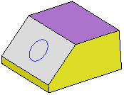
In the example below, the Add Extrude function is to be used to extrude the circle.
|
Extrude the circle. |
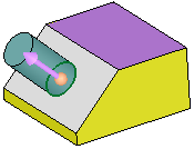
By default, the extrude direction is normal to the plane/face of the entity. |
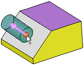
To select another direction, select the arrow base. |
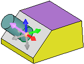
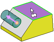
A toolbar of direction options is displayed. For this example, select the Normal to Reference option |
|
|
|
|
|
Pick a curve, plane or face.
1. If a plane or planar face is selected, the direction vector is normal to it.
2. If a non-planar face is selected, you are prompted to pick a point on the face. The direction vector is normal to the face at the selected point.
3. If a curve is selected, you are prompted to pick a point on the curve. The direction vector is normal to the curve at the selected point.
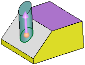
To flip the direction 180 degrees, select the arrow body (head or shaft).
|
Reference entity: |
Result: |
|
|
|


